
Channel Selection for DI-500/510/750/760 Series Instruments
The following procedure is used to specify the ADC channels to be acquired and whether these channels are configured for differential or digital operation.
To enable or configure channels for acquisition, you must be in the SET-UP operating mode. Channels cannot be added to, deleted from, or configured in the data acquisition file once the RECORD mode has been entered. To activate ADC channel configuration:
![]() In
the Edit menu click on Channels….
In
the Edit menu click on Channels….
OR
Double-click on theChannels: fieldin the status bar.
![]() Choose
Edit Channels… (ALT, E, C).
Choose
Edit Channels… (ALT, E, C).
This displays the channel selection grid.
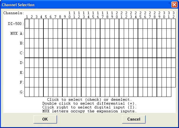
Each box in this grid represents an input channel. An input channel is enabled by clicking the desired box. Where in the grid you click, which mouse button you click with, and how many times you click the mouse button determines whether the input channel is enabled for differential operation, for operation defined by the 5B module (if used), or for differential operation between a pair of channels (automatically defined by the grid).
Since there are many variables, each instrument will be presented individually.
DI-500-16 and DI-750-16 | DI-500-32 and DI-750-32 | DI-510-32 and DI-760-32 | DI-510-48 and DI-760-48 | DI-510-64 and DI-760-64
DI-500-32X and DI-750-32X | DI-510-32X and DI-760-32X | DI-510-64X and DI-760-64X
Channels 1 through 16 are enabled on the top row of the grid.
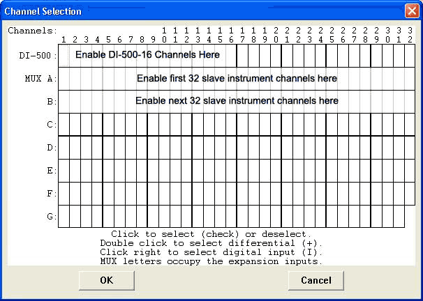
When other instruments are connected as a slave to the DI-500-16, their channels are enabled starting with row “MUX A” (and “B”, etc. when more than 32 channels are multiplexed). This is why you labeled the slave instrument input channels A1 through A32, B1 through B32, etc., during installation.
If a second DI-500-16 is multiplexed as a slave to the first DI-500-16, enable all 32 channels on the top row of the grid (ignore row “MUX A” and below). No other expansion is permitted when two DI-500-16’s are multiplexed. In this case, the expansion cable is connected from the EXPANSION connector on the master to the AUXILIARY PORT connector on the slave.
![]() Point
to the box in the grid that represents the desired channel and click
the left mouse button to enable the channel as a differential
input (when not using 5B modules) or as an input
defined by the 5B module (when used). A check mark is displayed
in the desired channel box, indicating that a differential input (when
not using 5B modules) or an input defined by the 5B module (when used)
has been enabled. A second activation removes the checkmark and thus disables
the channel.
Point
to the box in the grid that represents the desired channel and click
the left mouse button to enable the channel as a differential
input (when not using 5B modules) or as an input
defined by the 5B module (when used). A check mark is displayed
in the desired channel box, indicating that a differential input (when
not using 5B modules) or an input defined by the 5B module (when used)
has been enabled. A second activation removes the checkmark and thus disables
the channel.
![]() Point
to the box in the grid that represents the desired channel and double-click
the left mouse button to enable a pair
of differential channels for differential operation (this allows
you to see the difference between 2 differential input channels). A plus
sign (+) is displayed in the desired channel box, indicating one differential
channel and a minus sign (—) is automatically displayed eight channels
away (i.e., channels 1 and 9, 2 and 10, 5 and 13, etc.), indicating the
other differential channel. You can select the first or positive channel
(from 1 through 8), but the second or negative channel is automatically
selected by the software. Clicking the left mouse button on the plus sign
removes both plus and minus signs and thus disables the channel pair.
Point
to the box in the grid that represents the desired channel and double-click
the left mouse button to enable a pair
of differential channels for differential operation (this allows
you to see the difference between 2 differential input channels). A plus
sign (+) is displayed in the desired channel box, indicating one differential
channel and a minus sign (—) is automatically displayed eight channels
away (i.e., channels 1 and 9, 2 and 10, 5 and 13, etc.), indicating the
other differential channel. You can select the first or positive channel
(from 1 through 8), but the second or negative channel is automatically
selected by the software. Clicking the left mouse button on the plus sign
removes both plus and minus signs and thus disables the channel pair.
This configuration is useful anytime you need to monitor the difference between two differential input channels. For example, say we are monitoring the temperature of a long, narrow widget. We want the widget to be of uniform temperature throughout its entire length. We could use two thermocouples (one per channel, on each end of the widget) to monitor temperature. The temperature of one end of the widget would be measured by one thermocouple and the temperature of the other end of the widget would be measured by the other thermocouple. However, in the differential channel pair configuration as described above, only the difference between the two thermocouples would be reported by WinDaq software. This difference in temperature could then be used to control a process (i.e., if one end is 5° hotter than the other, then turn on a heater to evenly distribute the widget temperature).
![]() Point
to the box in the grid that represents the desired channel and click
the right mouse button to enable the channel as a digital
input. An “I” is displayed in the desired channel box, indicating
that a digital input has been enabled. Pointing to the “I” and clicking
the left mouse button removes the “I” and thus disables the channel. The
digital inputs are connected to the 37-pin AUXILIARY PORT connector on
the DI-500-16 instrument. Note that when you specify a channel as a digital
input in the channel selection grid, you no longer have the ability to
connect an analog signal to that channel either at the sheathed banana
jacks or at the screw terminals.
Point
to the box in the grid that represents the desired channel and click
the right mouse button to enable the channel as a digital
input. An “I” is displayed in the desired channel box, indicating
that a digital input has been enabled. Pointing to the “I” and clicking
the left mouse button removes the “I” and thus disables the channel. The
digital inputs are connected to the 37-pin AUXILIARY PORT connector on
the DI-500-16 instrument. Note that when you specify a channel as a digital
input in the channel selection grid, you no longer have the ability to
connect an analog signal to that channel either at the sheathed banana
jacks or at the screw terminals.
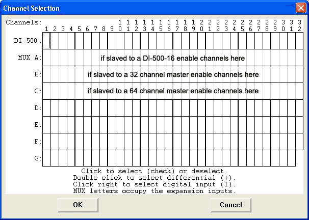
Ignore the top row. Channels 1 through 32 are enabled on the second row from the top (row “MUX A”).
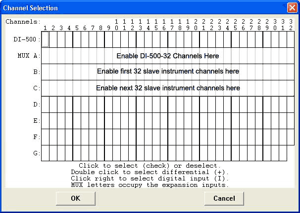
When other instruments are connected as a slave to the DI-500-32, their channels are enabled starting with row “B” (and “C”, etc. when more than 32 channels are multiplexed). This is why you labeled the slave instrument input channels B1 through B32, C1 through C32, etc., during installation.
![]() Point
to the box in the grid that represents the desired channel and click
the left mouse button to enable the channel as a differential input
(when not using 5B modules) or as an input
defined by the 5B module (when used). A check mark is displayed
in the desired channel box, indicating that a differential input (when
not using 5B modules) or an input defined by the 5B module (when used)
has been enabled. A second activation removes the checkmark and thus disables
the channel.
Point
to the box in the grid that represents the desired channel and click
the left mouse button to enable the channel as a differential input
(when not using 5B modules) or as an input
defined by the 5B module (when used). A check mark is displayed
in the desired channel box, indicating that a differential input (when
not using 5B modules) or an input defined by the 5B module (when used)
has been enabled. A second activation removes the checkmark and thus disables
the channel.
On this instrument, the plus sign (+) and the check mark both mean the channel is enabled as a differential input (when not using 5B modules) or as an input defined by the 5B module (when used). Clicking or double-clicking with the left mouse button accomplishes the same result (differential channel pairs are not supported on this instrument). Digital inputs are not supported on this instrument.
Ignore the top row. Channels 1 through 32 are enabled on the second row from the top (row “MUX A”).

When other instruments are connected as a slave to the DI-510-32, their channels are enabled starting with row “B” (and “C”, etc. when more than 32 channels are multiplexed). This is why you labeled the slave instrument input channels B1 through B32, C1 through C32, etc., during installation.
![]() Point
to the box in the grid that represents the desired channel and click
the left mouse button to enable the channel as a differential input
(when not using 5B modules) or as an input
defined by the 5B module (when used). A check mark is displayed
in the desired channel box, indicating that a differential input (when
not using 5B modules) or an input defined by the 5B module (when used)
has been enabled. A second activation removes the checkmark and thus disables
the channel.
Point
to the box in the grid that represents the desired channel and click
the left mouse button to enable the channel as a differential input
(when not using 5B modules) or as an input
defined by the 5B module (when used). A check mark is displayed
in the desired channel box, indicating that a differential input (when
not using 5B modules) or an input defined by the 5B module (when used)
has been enabled. A second activation removes the checkmark and thus disables
the channel.
On this instrument, the plus sign (+) and the check mark both mean the channel is enabled as a differential input (when not using 5B modules) or as an input defined by the 5B module (when used). Clicking or double-clicking with the left mouse button accomplishes the same result (differential channel pairs are not supported on this instrument). Digital inputs are not supported on this instrument.
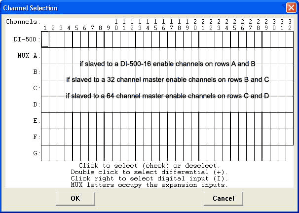
Channels 1 through 16 are enabled on the top row of the grid. Channels A1 through A32 are enabled on the second row from the top (row “MUX A”).
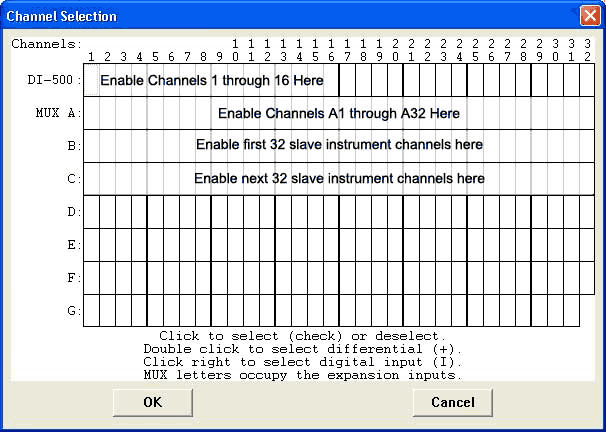
When other instruments are connected as a slave to the DI-510-48, their channels are enabled starting with row “B” (and “C”, etc. when more than 32 channels are multiplexed). This is why you labeled the slave instrument input channels B1 through B32, C1 through C32, etc., during installation.
![]() Point
to the box in the grid that represents the desired channel and click
the left mouse button to enable the channel as a differential
input (when not using 5B modules) or as an input
defined by the 5B module (when used). A check mark is displayed
in the desired channel box, indicating that a differential input (when
not using 5B modules) or an input defined by the 5B module (when used)
has been enabled. A second activation removes the checkmark and thus disables
the channel.
Point
to the box in the grid that represents the desired channel and click
the left mouse button to enable the channel as a differential
input (when not using 5B modules) or as an input
defined by the 5B module (when used). A check mark is displayed
in the desired channel box, indicating that a differential input (when
not using 5B modules) or an input defined by the 5B module (when used)
has been enabled. A second activation removes the checkmark and thus disables
the channel.
![]() Point
to the box in the grid that represents the desired channel and double-click
the left mouse button to enable a pair
of differential channels for differential
operation (this allows you to see the difference between 2 differential
input channels). A plus sign (+) is displayed in the desired channel box,
indicating one differential channel and a minus sign (-) is automatically
displayed eight channels away (i.e., channels 1 and 9, 2 and 10, 5 and
13, etc.), indicating the other differential channel. You can select the
first or positive channel (from 1 through 8), but the second or negative
channel is automatically selected by the software. Clicking the left mouse
button on the plus sign removes both plus and minus signs and thus disables
the channel pair.
Point
to the box in the grid that represents the desired channel and double-click
the left mouse button to enable a pair
of differential channels for differential
operation (this allows you to see the difference between 2 differential
input channels). A plus sign (+) is displayed in the desired channel box,
indicating one differential channel and a minus sign (-) is automatically
displayed eight channels away (i.e., channels 1 and 9, 2 and 10, 5 and
13, etc.), indicating the other differential channel. You can select the
first or positive channel (from 1 through 8), but the second or negative
channel is automatically selected by the software. Clicking the left mouse
button on the plus sign removes both plus and minus signs and thus disables
the channel pair.
This configuration is useful anytime you need to monitor the difference between two differential input channels. For example, say we are monitoring the temperature of a long, narrow widget. We want the widget to be of uniform temperature throughout its entire length. We could use two thermocouples (one per channel, on each end of the widget) to monitor temperature. The temperature of one end of the widget would be measured by one thermocouple and the temperature of the other end of the widget would be measured by the other thermocouple. However, in the differential channel pair configuration as described above, only the difference between the two thermocouples would be reported by WinDaq software. This difference in temperature could then be used to control a process (i.e., if one end is 5° hotter than the other, then turn on a heater to evenly distribute the widget temperature).
![]() Point
to the box in the grid that represents the desired channel and click
the right mouse button to enable the channel as a digital
input. An “I” is displayed in the desired channel box, indicating
that a digital input has been enabled. Pointing to the “I” and clicking
the left mouse button removes the “I” and thus disables the channel.
The digital inputs are connected to the 37-pin AUXILIARY PORT connector
on the DI-510-48 instrument. Note that when you specify a channel as a
digital input in the channel selection grid, you no longer have the ability
to connect an analog signal to that channel either at the sheathed banana
jacks or at the screw terminals.
Point
to the box in the grid that represents the desired channel and click
the right mouse button to enable the channel as a digital
input. An “I” is displayed in the desired channel box, indicating
that a digital input has been enabled. Pointing to the “I” and clicking
the left mouse button removes the “I” and thus disables the channel.
The digital inputs are connected to the 37-pin AUXILIARY PORT connector
on the DI-510-48 instrument. Note that when you specify a channel as a
digital input in the channel selection grid, you no longer have the ability
to connect an analog signal to that channel either at the sheathed banana
jacks or at the screw terminals.
Ignore the top row. All 64 channels (two rows of 32) are enabled on the second and third rows from the top (rows “MUX A” and “B”).
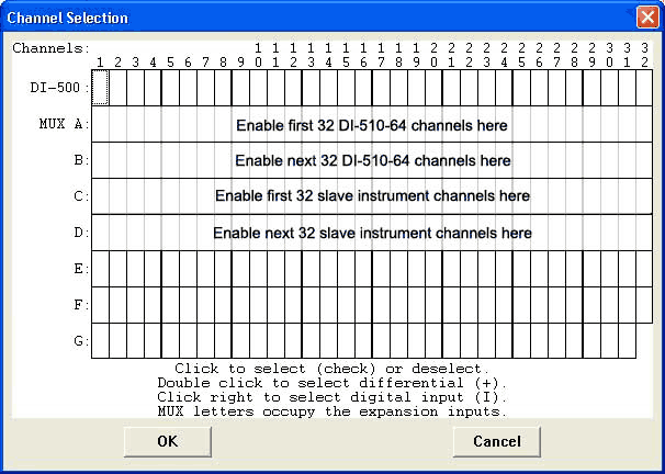
When other instruments are connected as a slave to the DI-510-64, their channels are enabled starting with row “C” (and “D”, etc. when more than 32 channels are multiplexed). This is why you labeled the slave instrument input channels C1 through C32, D1 through D32, etc., during installation.
![]() Point
to the box in the grid that represents the desired channel and click
the left mouse button to enable the channel as a
differential input (when not using 5B modules) or as an input
defined by the 5B module (when used). A check mark is displayed
in the desired channel box, indicating that a differential input (when
not using 5B modules) or an input defined by the 5B module (when used)
has been enabled. A second activation removes the checkmark and thus disables
the channel.
Point
to the box in the grid that represents the desired channel and click
the left mouse button to enable the channel as a
differential input (when not using 5B modules) or as an input
defined by the 5B module (when used). A check mark is displayed
in the desired channel box, indicating that a differential input (when
not using 5B modules) or an input defined by the 5B module (when used)
has been enabled. A second activation removes the checkmark and thus disables
the channel.
On this instrument, the plus sign (+) and the check mark both mean the channel is enabled as a differential input (when not using 5B modules) or as an input defined by the 5B module (when used). Clicking or double-clicking with the left mouse button accomplishes the same result (differential channel pairs are not supported on this instrument). Digital inputs are not supported on this instrument.
When using expansion instruments, always enable the master instrument channels first. Channels 1 through 32 of the DI-500-32-DX (or -PX) can then be enabled after the master instrument channels. For example, say you are using a DI-510-32-P as a master and the DI-500-32-PX as a slave. You would enable channels 1 through 32 of the DI-500-32-PX on row “B.”
![]() Point
to the box in the grid that represents the desired channel and click
the left mouse button to enable the channel as a differential
input (when not using 5B modules) or as an input
defined by the 5B module (when used). A check mark is displayed
in the desired channel box, indicating that a differential input (when
not using 5B modules) or an input defined by the 5B module (when used)
has been enabled. A second activation removes the checkmark and thus disables
the channel.
Point
to the box in the grid that represents the desired channel and click
the left mouse button to enable the channel as a differential
input (when not using 5B modules) or as an input
defined by the 5B module (when used). A check mark is displayed
in the desired channel box, indicating that a differential input (when
not using 5B modules) or an input defined by the 5B module (when used)
has been enabled. A second activation removes the checkmark and thus disables
the channel.
On this instrument, the plus sign (+) and the check mark both mean the channel is enabled as a differential input (when not using 5B modules) or as an input defined by the 5B module (when used). Clicking or double-clicking with the left mouse button accomplishes the same result (differential channel pairs are not supported on this instrument). Digital inputs are not supported on this instrument.
When using expansion instruments, always enable the master instrument channels first. Channels 1 through 32 of the DI-510-32 can then be enabled after the master instrument channels. For example, say you are using a DI-510-32-P as a master and the DI-510-32-PX as a slave. You would enable channels 1 through 32 of the DI-510-32-PX on row “B.”
![]() Point
to the box in the grid that represents the desired channel and click
the left mouse button to enable the channel as a differential
input (when not using 5B modules) or as an input
defined by the 5B module (when used). A check mark is displayed
in the desired channel box, indicating that a differential input (when
not using 5B modules) or an input defined by the 5B module (when used)
has been enabled. A second activation removes the checkmark and thus disables
the channel.
Point
to the box in the grid that represents the desired channel and click
the left mouse button to enable the channel as a differential
input (when not using 5B modules) or as an input
defined by the 5B module (when used). A check mark is displayed
in the desired channel box, indicating that a differential input (when
not using 5B modules) or an input defined by the 5B module (when used)
has been enabled. A second activation removes the checkmark and thus disables
the channel.
On this instrument, the plus sign (+) and the check mark both mean the channel is enabled as a differential input (when not using 5B modules) or as an input defined by the 5B module (when used). Clicking or double-clicking with the left mouse button accomplishes the same result (differential channel pairs are not supported on this instrument). Digital inputs are not supported on this instrument.
When using expansion instruments, always enable the master instrument channels first. All 64 channels (two rows of 32) of the DI-510-64-DX (or -PX) can then be enabled after the master instrument channels. For example, say you are using a DI-510-64-P as a master and the DI-510-64-PX as a slave. You would enable the first 32 channels of the DI-510-64-PX on row “C,” and the second group of 32 channels on row “D.”
![]() Point
to the box in the grid that represents the desired channel and click
the left mouse button to enable the channel as a differential
input (when not using 5B modules) or as an input
defined by the 5B module (when used). A check mark is displayed
in the desired channel box, indicating that a differential input (when
not using 5B modules) or an input defined by the 5B module (when used)
has been enabled. A second activation removes the checkmark and thus disables
the channel.
Point
to the box in the grid that represents the desired channel and click
the left mouse button to enable the channel as a differential
input (when not using 5B modules) or as an input
defined by the 5B module (when used). A check mark is displayed
in the desired channel box, indicating that a differential input (when
not using 5B modules) or an input defined by the 5B module (when used)
has been enabled. A second activation removes the checkmark and thus disables
the channel.
On this instrument, the plus sign (+) and the check mark both mean the channel is enabled as a differential input (when not using 5B modules) or as an input defined by the 5B module (when used). Clicking or double-clicking with the left mouse button accomplishes the same result (differential channel pairs are not supported on this instrument). Digital inputs are not supported on this instrument.