
Configure Channels > For All Other Products Activating Procedure
To enable or configure channels for acquisition, WinDaq must be in the SET-UP operating mode. Channels cannot be added, deleted, or configured once the user has entered the RECORD mode.
![]() Click
on the Enable button in the Toolbox.
Click
on the Enable button in the Toolbox.
![]() In
the Edit menu click on Channels...
or double-click on the Channels:
field
in the status bar. This displays the Channel Selection grid.
In
the Edit menu click on Channels...
or double-click on the Channels:
field
in the status bar. This displays the Channel Selection grid.
DI-2108-P instruments allow for multiple synced devices (ChannelStretch™) to acquire data at the same time. Devices are listed in alpha-numeric order based on serial number (the serial number is printed on the bottom sticker of the device).
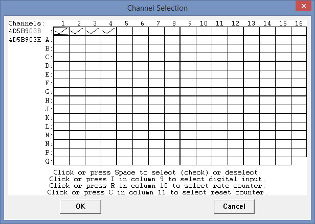
When acquiring data from multiple DI-2108-P devices, the number of channels enabled must be the same for each device (the channels do not need to be the same channels).
Enabling a channel in the grid flashes the selected device LED white.

The current status of all channels is displayed in this grid. The Channel Selection grid allows the user to enable and disable analog and digital input channels. All channels are enabled/disabled with a left-click on the channel box. Analog Input channels show a checkmark when enabled. Channels enable for Thermocouple input display a "T" when enabled.
Thermocouple Channels are specified using the Input Type in Edit > Channel Settings.
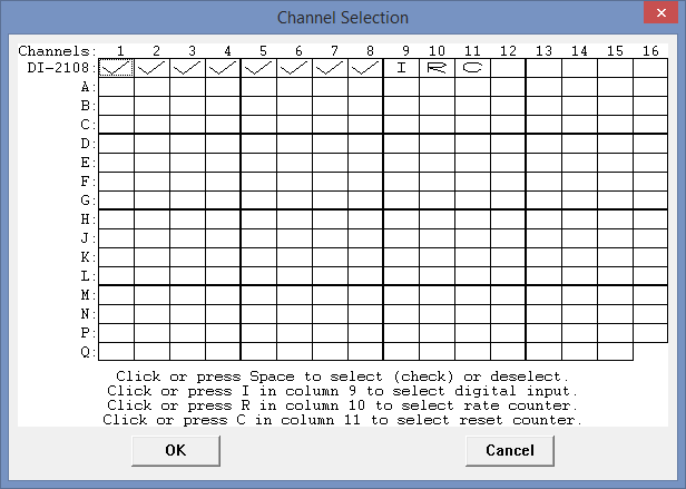
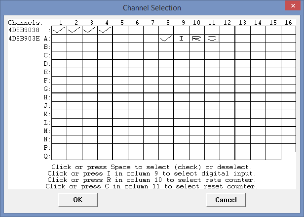
The current status of all channels is displayed in this grid. The Channel Selection grid allows the user to enable and disable analog and digital input channels. All channels are enabled/disabled with a left-click on the channel box. Analog Input channels show a checkmark when enabled. The Digital Input channels (channels 9 (general purpose digital input - "I"), 10 (Rate channel - "R"), and 11 (Count channel - "C")) show an I, R, or C, respectively when enabled.
Enable channel 9 to monitor the state of the 4 digital input bits. Digital data can be plotted and viewed by selecting Scaling > Digital Plot. This feature horizontally splits the top half of the waveform strip on channel 9 for digital inputs into equal parts. The top-most is assigned to digital input 0, the bottom-most digital input 3, with the remaining 2 digital inputs allocated in logical order within the strip. This feature provides quick-look capability to determine the state of a digital input line. See also Digital Input channel.
The current status of all channels is displayed in this grid. The Channel Selection grid allows the user to enable and disable channels. Click on the channel 9 box to enable the digital input channel. Click on the channel 10 box to enable the Rate channel. Click on the channel 11 box to enable the Counts channel.
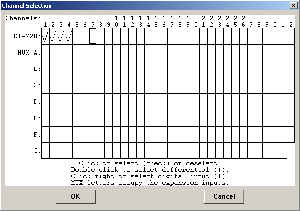
The current status of all channels is displayed in this grid. The Channel Selection grid allows the user to enable and disable channels. In the illustration above, the boxes formed by the top row of the grid represent the internal channels available on the hardware device (the corresponding channel number is positioned on top of the row). In this example, a DI-720 was used and configured for channels 1-4 as single-ended inputs and channel 7 as a differential input. The subsequent rows underneath the top row of the grid (labeled A, B, C, etc.) represent each group of 32 external analog input channels which may be activated through use of an analog channel expander (DI-725 or DI-75B).
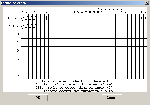
In the next graphic, a single DI-725 32-channel analog expander is added to the original DI-720. This allows Row A to be used to enable and disable channels on the analog expander. At the end of the row labeled DI-720, you’ll notice a pair of “A”s in the 31 and 32 positions. This indicates that the DI-725 is active and successfully communicating with the DI-720. It also indicates that channels 31 and 32 of the DI-720 are multiplexed through the DI-725. These channels on the DI-720 are, therefore, no longer available for direct input. Channel 31 multiplexes the first 16 channels or the attached channel expander and channel 32 multiplexes the next 16 channels. If a second expander is added, channels 29 and 30 would contain “B” indicating they are being used by the second expander. Each expander added continually increments channels in this manner.
A channel is enabled for single-ended, differential, or digital input by specific actions. These actions are described below.
Enabling/disabling a single-ended channel or fixed differential channel
Only pertains to internal [top row] analog inputs. Point to the box in the grid representing the desired channel and click the left mouse button. A checkmark will be displayed in the desired channel box, indicating that the channel has been enabled and designated as single-ended. Clicking on the left mouse button where a channel already has a check mark removes the checkmark and thus disables the channel. Enable fixed differential channels in the same manner. See your hardware manual to determine whether you instrument has fixed differential channels or not.
Enabling/disabling a differential channel
Point to the box in the grid representing the desired channel and double-click the left mouse button. A plus sign (+) will be displayed in the desired channel box, indicating that the channel has been enabled and designated as differential. Double-clicking a second time removes the plus sign and thus disables the channel.
Note that it is not possible to enable a differential channel numbered higher than one half the total number of channels provided by the device (assuming the device supports differential inputs). A differential channel requires two input terminals (positive and negative). For example, in order to designate channel 1 as differential requires both the channel 1 input terminal (positive input) and the channel 9 input terminal (negative input). For this same reason, when a differential channel is enabled, its corresponding input is marked with a minus sign (-) in the Channel Selection grid, indicating that it is the low input of the differential pair.
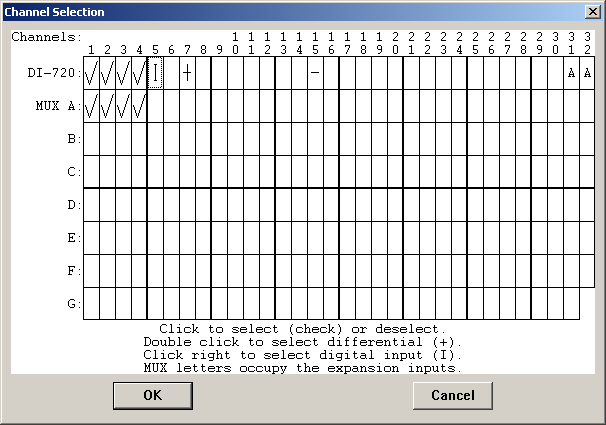
Enabling a digital input channel
Point to the box in the grid representing the desired channel and click the right mouse button. An “I” will be displayed in the desired channel box, indicating that the channel has been enabled and designated as digital.
To disable a digital input channel point to the box in the grid that contains the "I" and click the left mouse button. When a channel is enabled as a digital input, WinDaq Acquisition is directed to acquire the eight digital input bits, which are accessible as defined by the hardware. When the digital value is acquired, it is scaled between +128 and -128, with 0 in the center. As the levels connected to the digital inputs change state, the corresponding digital value will be displayed by WinDaq Acquisition in the channel enabled as a digital input.
An alternate method to plotting digital data can be enabled by selecting Scaling > Digital Plot. This feature horizontally splits the waveform strip that is configured for digital input into eight equal parts. The top-most is assigned to digital input 0, the bottom-most digital input 7, with the remaining 6 digital inputs allocated in logical order within the strip. This feature provides quick-look capability to determine the state of a digital input line. See also Digital Input channel.