Note:
Not available with all instruments.
Allows you to remotely trigger event markers and data storage to disk through the remote Storage and Remote Event digital input ports using a TTL level signal or switch.
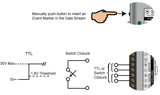
The DI-145 and DI-245 support several methods to increase measurement flexibility and data record interpretation. The remote record feature allows you to synchronize WinDaq recordings to external processes by remotely enabling and disabling WinDaq’s stream-to-disk feature. Remote events allow you to insert an event marker in the data stream to identify when an event occurred relative to recorded waveform activity. Events can be activated by the pushbutton on the DI-145 enclosure, though a keyboard keystroke (which also allows you to record a description), or remotely via the remote event input. The stream-to-disk function can also be controlled through the keyboard, or through the remote record input. Valid remote record and event signals are switch closures, or discrete levels with a maximum input of 30 V and a threshold of 1.8 V.
The DI-149 and DI-155 support several methods to increase measurement flexibility and data record interpretation. The remote record feature allows you to synchronize WinDaq recordings to external processes by remotely enabling and disabling WinDaq’s stream-to-disk feature. Remote events allow you to insert an event marker in the data stream (see inset) to identify when an event occurred relative to recorded waveform activity. Events can be activated by the pushbutton on the DI-149 enclosure, through a keyboard keystroke (which also allows you to record a description), or remotely via the remote event input. The stream-to-disk function can also be controlled through the keyboard, or through the remote record input. Valid remote record and event signals are switch closures, or discrete levels with a maximum input of 30 V and a threshold of 1.8 V.

The digital input pins on the DI-149, DI-155, and DI-245 are clearly labeled on the device: Remote Events = Evnt/DI0; Remote Storage = Rcrd/D1.
These ports are labeled differently for each instrument. See the table below for location of the remote digital ports.
|
Instrument |
Remote Event |
Remote Start/Stop |
|
DI-148U |
D1 Event |
D0 Record |
| DI-149 and DI-155 | Evnt/DI0 | Rcrd/D1 |
|
DI-151 |
Dig 0 |
Dig 1 |
|
DI-154RS* |
Dig 1 |
Dig 1 |
|
DI-158 Series |
D1 Event |
D0 Record |
|
DI-194 |
D0 |
D1 |
|
DI-194RS* |
Dig 1 |
Dig 1 |
|
DI-220 Series |
DI0 |
DI1 |
|
DI-400 Series |
DI0 |
DI1 |
|
DI-500/510 Series |
REMOTE EVENTS |
REMOTE STOP/START |
|
DI-700 Series |
DI0 |
DI1 |
|
DI-710 Series* |
D1 = Remote Event |
D0 = Remote Start/Stop |
|
DI-720 Series |
R. START/STOP |
EVNT |
|
DI-730 Series |
R. START/STOP |
EVNT |
|
DI-750/760 Series |
REMOTE EVENTS |
REMOTE STOP/START |
|
DI-2108 Series |
D0 |
D1 |
*Note to DI-194RS and DI-154RS users: Dig 1 can be used for Remote Event OR Remote Start/Stop. Do Not use Dig 0.
*Note to DI-710 users: To access the Remote Control features, you must have Channel 1 or Channel 17 enabled as the digital input and the first two digital bits must be set as inputs using the DATAQ Instruments Hardware Manager D0 for Remote Start/Stop and D1 for Remote Event.