|
|
|
|
Channel Settings > Activating Procedure |
|
Since most of the settings this function displays can be assigned on a per-channel basis in WinDaq recording software, the desired channel must first be selected.
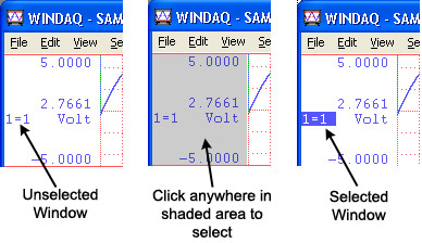
1. Select the desired channel:
![]() Click
the left mouse button in the desired channel’s annotation margin.
Click
the left mouse button in the desired channel’s annotation margin.
![]() Type
the window number that contains the desired channel.
Type
the window number that contains the desired channel.
2. With the desired channel selected, select Channel Settings…
![]() In
the View menu click on Channel
Settings….
In
the View menu click on Channel
Settings….
![]() Choose
View Channel Settings… (ALT, V, C).
Choose
View Channel Settings… (ALT, V, C).
This displays the Channel Settings dialog box.
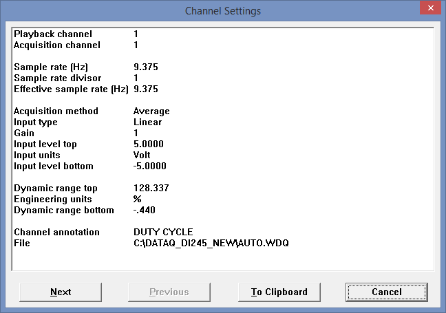
The Next and Previous command buttons allow you to step through all of the enabled channels in order, viewing the channel settings for each enabled channel without closing this dialog box.
The To Clipboard command button allows you to send all of the information in this dialog box to the clipboard in text format, ideal for pasting into a word processor or spreadsheet. Since the information pasted from the clipboard is in text format (not a bitmap), the values are separated from the settings labels by tabs and can easily be edited with your word processor or spreadsheet program.
The following describes each item in the Channel Settings dialog box (these items are originally set from within WinDaq recording software by choosing Channel Settings… from the Edit menu.
Playback channel - Displays the channel you are currently viewing the settings for.
Acquisition channel - Displays the physical channel number that was used during recording. If None is displayed, it means this channel was never recorded but instead is a “calculated” channel, created by Advanced CODAS Analysis Software (available as an extra-cost option).
Sample rate (Hz) - Displays the sample rate (in Hz) that was used to record this channel.
Sample rate divisor - Displays the sample rate divisor that was used for this channel to achieve a specific sample rate. Note that if the channel was recorded with WinDaq/Pro+ recording software, this divisor can range from 1 to 255, indicating the factor that was used to divide the per-channel sample rate to a desired value, otherwise this will always be 1.
Effective sample rate (Hz) - Displays the channels effective sample rate. When the sample rate divisor is 1, the effective sample rate is the same as the sample rate. When a sample rate divisor other than 1 is used, the effective sample rate describes the rate at which data was recorded to disk.
When a sample rate divisor other than 1 is used on a channel, the sample rate still accurately describes the rate at which data gets sampled, but does not accurately describe the rate at which data was recorded to disk. This is why we need a new value, called “effective sample rate”. It takes into account the original sample rate, the number of enabled channels, and the sample rate divisor of all enabled channels.
Acquisition method - Displays the method chosen for displaying data on your monitor and recording it to disk. Valid displays are Average, Last Point, Maximum, Minimum, RMS, or Frequency.
Input type - Displays the type of transducer originally used on this channel to record the data. Valid displays are Linear, Thermocouple, and Nonlinear.
Gain - Displays the gain chosen for this channel prior to recording. Gain factors vary by instrument.
Input level top - Displays the input level at the top of the A/D converter’s range. This value will be a voltage (either +5.00 or +10.00 volts) if the channel was truly used for recording, or it will be expressed as a percentage of full scale (+100.00%) if this is a “calculated” channel created by Advanced CODAS Analysis Software.
Input units - Displays volts if the channel was used for recording, or displays %FS (percent full scale) if the channel is a “calculated” channel created by Advanced CODAS Analysis Software.
Input level bottom - Displays the input level at the bottom of the A/D converter’s range. This value is a voltage (either -5.00 or -10.00 volts) if the channel was truly used for recording, or it will be expressed as a percentage of full scale (-100.00%) if this is a “calculated” channel created by Advanced CODAS Analysis Software.
Dynamic range top - Displays the engineering unit value at the top of the A/D converter’s range. This value will be an engineering unit value if the channel was calibrated in WinDaq Acquisition Software, or it will be expressed as a percentage of full scale (+100.00%) if the channel was not calibrated.
Engineering units - Displays the units used to calibrate the waveform in WinDaq Acquisition, or it displays %FS (percent full scale) if the channel was not calibrated. See EU Settings.
Dynamic range bottom - Displays the engineering unit value at the bottom of the A/D converter’s range. This value will be an engineering unit value if the channel was calibrated in WinDaq Acquisition Software, or it will be expressed as a percentage of full scale (-100.00%) if the channel was not calibrated.
Channel annotation - Displays any channel specific user annotation that may have been entered during recording.
File - Displays the name and path of the file you’re working with.