
Drawing Selection Rectangles
Drawing Selection Rectangles
In WinDaq Acquisition,
you can draw a graphic selection rectangle and just a plain selection
rectangle. A graphic selection rectangle is used to copy the graphics
bounded by the graphic selection rectangle (drawn with the mouse) to the
clipboard. The selection rectangle is used with the mouse just to offset
and/or scale a waveform.
Both rectangles are drawn the same way, only
the graphic selection rectangle is created with the right mouse button
while the selection rectangle is created with the left mouse button.
A graphic selection rectangle is drawn by positioning
the mouse pointer anywhere in the waveform strip area and dragging with
the right mouse button until the rectangle encloses the area you wish
to copy to the clipboard. When the mouse button is released, the rectangle
remains fixed in size. You can now choose Copy from the Edit menu to copy
the enclosed graphics to the clipboard.
A selection rectangle is drawn by positioning
the mouse pointer anywhere in the waveform strip area and dragging with
the left mouse button until the rectangle reaches the desired size. When
the mouse button is released, the rectangle remains fixed in size. The
following examples illustrate how the selection rectangle can be used
in typical offsetting and scaling operations.
Offsetting
a Specified Channel’s Waveform
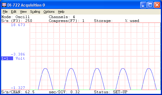
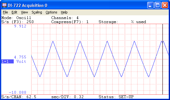
- The
original waveform. The object is to offset the waveform from its current
position to a position centered on the screen. Note that the “1=1” annotation
in the left annotation margin is highlighted, indicating window 1 is enabled
for adjustments.
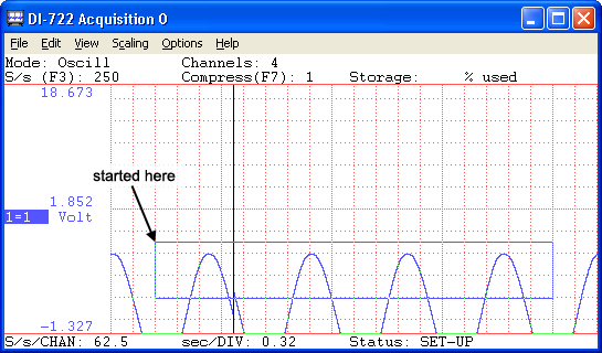
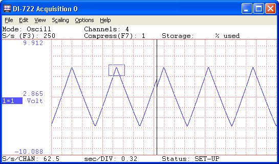
- Drag the left mouse button
to draw a selection rectangle. The size (and placement) of the rectangle
is immaterial. In this example, it was drawn to approximate the vertical
limits of the waveform so it could be accurately centered at the center
of the screen. Note that the rectangle remains fixed in size when the
left mouse button is released.
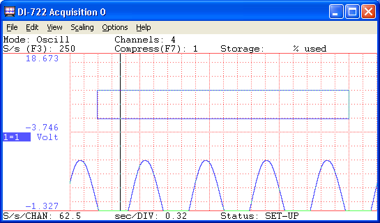
- With the mouse pointer
positioned inside the selection rectangle, drag the rectangle to achieve
the desired offset (in this example, vertically centered at the center
of the screen).
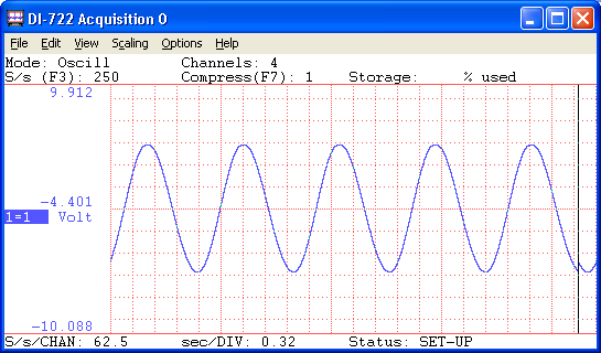
- The offset waveform.
When the left mouse button was released, the waveform was vertically offset
by the amount the rectangle was dragged (within the limits of the A/D
converter’s dynamic range). Note the waveform’s numerical values in the
left annotation margin reflect the new position.
Scaling
a Specified Channel’s Waveform
- The
original waveform. The object is to scale a small section of waveform
so it fills the entire strip area, thus allowing the small section to
be examined in greater detail. Again note that the “1=1” annotation in
the left annotation margin is highlighted, indicating window 1 is enabled
for adjustments.
- Drag
the left mouse button to draw a selection rectangle. Once again, the size
of the rectangle is immaterial. In this example, it was drawn on the very
tip of the waveform because this is the area of interest that we would
like to examine in greater detail. Note that the rectangle remains fixed
in size when the left mouse button is released.
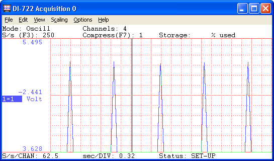
- The scaled waveform,
accomplished by clicking the left mouse button in the left annotation
margin. The contents of the selection rectangle have been scaled to fill
the entire waveform strip area.
Top