
Preferences > Frequency
Allows you to set Frequency preferences when using the Frequency Acquisition Method.
![]() In
the Preferences sub-menu click
on Frequency....
In
the Preferences sub-menu click
on Frequency....
![]() Choose
Edit Preferences Frequency... (ALT, E, P, Q).
Choose
Edit Preferences Frequency... (ALT, E, P, Q).
The Frequency dialog box will display.
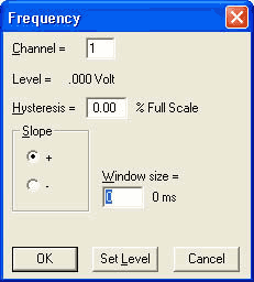
Channel = Sets the trigger channel.
Hysteresis = Sets the hysteresis level based on a percentage of the Full Scale. For example, assuming a Positive Full Scale value of 10 Volts - 1% is equal to 0.1 Volts. In this example, if your trigger level is set to 5 volts triggering will occur at 5.05 or 4.95 volts depending on the slope setting (positive (+) or negative (-)) and not again until the signal reaches the opposite rearm level. This prevents multiple triggering on a noisy slowly-moving transition.
Window size = The number of samples being calculated to display converted data. This should be set to at least as many samples as the maximum sample rate per channel (the maximum sample rate per channel is the maximum sample rate divided by the number of enabled channels) divided by the lowest expected input frequency. Increasing the window size results in a more stable signal but can average out speed variations that may be of interest. After setting this value, use the TAB key to display the corresponding window time.
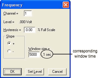
A window size of 5000 samples with a time of .1 seconds would mean that 5000 samples at the device burst rate per channel on the selected channel, spread out over .1 seconds, are used to calculate each frequency value - i.e., if you have the maximum sample rate set at 50000 and 1 channel enabled, the software takes 5000 samples over .1 seconds (i.e., out of 5000 samples) and calculates one frequency data point. With each new data point acquired by your device, the window moves and the frequency is recalculated.
Note: Since Frequency is recalculated with every newly-acquired data sample, multiple Frequency channels could cause gaps in data depending on the speed of your PC. If gaps occur, lower the Maximum Sample Rate until your PC can handle the load.
The highest input frequency that can be calculated is half the device burst rate divided by the number of channels. The device burst rate = the maximum sample rate if the maximum sample rate is an integral multiple of the total sample rate. Otherwise, the device burst rate will be at least half the maximum sample rate. A square wave input with 50% duty cycle will work best as the frequency approaches the limit.
Note: Subsequently changing the sample rate or number of channels will change the corresponding window time.
The Slope radio button allows you to set the trigger condition on either a positive going slope (+) or a negative going slope (-).
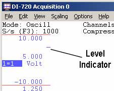
The Trigger Level can be set by selecting Set Level. After selecting Set Level a level indicator appears in your acquisition window. This level indicator can be moved up and down to select the trigger level. The graphic below shows a trigger level setting of 5 Volts.
Although multiple frequency channels may be enabled using different gains, the trigger level and hysteresis for all of them must be the same relative to the full-scale dynamic range.
After making the frequency settings you may now choose the frequency acquisition method in the channel settings dialog box. You may now change Hz to Cycles/min by clicking on the Cycles/min check box that appears when Frequency has been selected. See also Acquisition Method.
This method is not for use with the DI-400 Series instruments nor for instruments using a parallel port interface and running Windows 95 or 98. Contact DATAQ Instruments for more information.
When using the Frequency acquisition method it is important that you not set the Maximum Sample Rate higher than that allowed by your instrument. Doing so may cause your computer to freeze. If using a printer port device, it is important that you not exceed these maximum sample rates.
|
Devices |
Port Mode |
Maximum Samples/sec |
|
DI-500, DI-510, DI-720, DI-730 |
EPP (Enhanced Parallel Port) |
180,000 NT/2000/XP |
|
DI-500, DI-510, DI-720, DI-730 |
EPP (Enhanced Parallel Port) |
110,000 95/98/ME |
|
DI-500, DI-510, DI-720, DI-730 |
Bidirectional (PS/2) |
60,000 |
|
DI-500, DI-510, DI-720P, DI-730P |
Standard (Compatible, Unidirectional) |
30,000 |
|
DI-220, DI-221, DI-222 |
Bidirectional (PS/2) |
25,000 |
|
DI-220, DI-221, DI-222 |
Standard (Compatible, Unidirectional) |
12,500 |