|
|
|
|
IP Reference Info for non EN-A/EN-B Devices |
|
TCP/IP uses several basic pieces of information to successfully communicate between devices on networks. Two of these pieces of information are IP address and subnet mask.
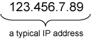
Every device (computer, DI-730-EN instrument, etc.) on a TCP/IP network has an IP address. This unique identification is typically represented using “dotted decimal notation.” In this format, each byte (8-bit segment) of the 32-bit IP address is represented by a decimal number (ranging from 0 to 255) and is separated by a period.
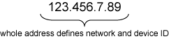
The four bytes of an IP address combine to convey two pieces of information: the network identification (it defines a group of computers and other devices on a given network) and the device identification (it defines a computer or other device within that network).
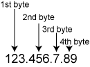
The first byte of an IP address identifies the network class. There are three different classes for accommodating networks of different sizes. With the network class defined by the first byte, all four bytes (the whole address) are used to define network ID and device ID. The table below shows how the network ID and device ID information is defined for each network class.
|
Network class |
Range of values for 1st byte |
Part of IP address that defines network ID |
Part of IP address that defines device ID |
Possible # of networks |
Possible # of devices/network |
|
A |
1-126 |
1st byte |
2nd, 3rd, and 4th bytes |
126 |
16,777,214 |
|
B |
128-191 |
1st and 2nd byte |
3rd and 4th byte |
16,384 |
65,534 |
|
C |
192-223 |
1st, 2nd, and 3rd bytes |
4th byte |
2,097,151 |
254 |
Notes: Address 127 in the 1st byte is reserved for testing and other purposes. Addresses 0 or 255 in any byte position and address 224 and above in the network ID part are reserved for special protocols.
Any in-house or private TCP/IP network that is not connected to the public Internet can use any network and device ID’s. For networks that connect to the public Internet, Internet Service Providers get official network IDs through the InterNIC (Internet Network Information Center).
A device uses the network ID and device ID to sort information traffic on the network or, in other words, determine what information it should receive or ignore. All devices connected to the same network must have the same network ID and subnet mask.
The purpose of the subnet mask is to define or separate the network ID and device ID portions of an IP address. Subnet masks are generally represented using the same “dotted decimal notation” described earlier, however the bit values themselves define the mask. Each bit assigned a “1” value in the subnet mask defines the corresponding bit of the IP address as a network ID bit. Bits assigned a “0” value identify the device ID part of the IP address. The following table shows default subnet masks:
|
Network class |
Dotted decimal notation |
Binary equivalent |
|
A |
255.0.0.0 |
11111111 00000000 00000000 00000000 |
|
B |
255.255.0.0 |
11111111 11111111 00000000 00000000 |
|
C |
255.255.255.0 |
11111111 11111111 11111111 00000000 |
For each network class, the subnet mask must at least use the “1” bits assigned in the default subnet masks listed above. However, any network class can be subdivided further by assigning “1” bits in the default “0” positions of the mask. This means that it is possible to create more subnets, but at the expense of fewer devices per subnet. In many cases, this type of subnet configuration is more appropriate than just using the default values.
Let's consider an example. Say we want to add a DI-730-EN to an existing Ethernet network. A look at the TCP/IP properties dialog box on the PC we're installing the DI-730-EN to reveals:
IP
address: 192.168.1.44
Subnet mask: 255.255.255.0
From this, we know that the PC is connected to a class C network, the network ID is 192.168.1 and the device ID (the PC itself) is 44. We also know that any other device added to this network must share the same network ID (192.168.1) and subnet mask (255.255.255.0), but must possess a unique device ID (an unused value from 1 to 254). So to add the DI-730-EN to this network, we must change the DI-730-EN’s IP address from its default, factory-assigned value. Information on how to do that is presented in the following section, titled “Changing an Instrument’s IP Address.”
Regardless of the number of interconnected subnetworks, the important thing to remember is all devices (PC’s, DI-730-EN’s, etc.) on the same subnet must use the same subnet mask and network ID to avoid conflicts. Never attempt to assign a device an address already used by another device on the same network. Each device on a network must have a unique IP address, valid for its particular network.
If you are configuring a private network (one that will not be connected to the public Internet or directly to an existing in-house network), you can select IP addresses from the Internet Assigned Numbers Authority (IANA) List of Reserved IP Addresses for Private Networks. These reserved address ranges are:
10.0.0.0
to 10.255.255.255
172.16.0.0 to 172.31.255.255
192.168.0.0 to 192.168.255.255
These addresses are ignored by Internet routers and therefore do not have to be globally unique. If you require further information, a document that describes these addresses (“RFC 1597: Address Allocation for Private Internets”) is available on the Internet.
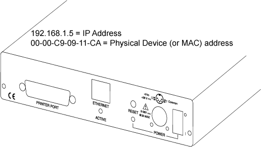
Each DI-720-EN, DI-722-EN, and DI-730-EN instrument is assigned an IP address before it is shipped. (Every instrument has an IP address, which is in addition to your computer’s IP address that was just checked/assigned in the previous procedure.) This IP address, along with the instrument’s physical device address (or MAC address), is printed on the bottom of the instrument. By default, all DI-720-EN, DI-722-EN, and DI-730-EN instruments are initially assigned the same IP address (192.168.1.5). However, the physical device address is unique for each instrument:
192.168.1.5 is assigned by default because it is reserved for use on private networks or, in other words, it will not be in use on the public Internet. As discussed in the previous section (titled “TCP/IP Reference Information”):
If (by slim probability) your network ID is 192.168.1, and device ID 5 is not being used by any other device on your network, then your DI-720-EN, DI-722-EN, or DI-730-EN will work “as is” and its IP address will never need to be changed. Most likely, there will be a conflict with your network ID, or device ID, or you may be connecting more than one DI-720-EN, DI-722-EN, or DI-730-EN instrument to your network. In these instances, you must change the DI-720-EN, DI-722-EN, or DI-730-EN instrument’s IP address so that each device has a unique identity on the network. Use the following procedure to change the DI-720-EN, DI-722-EN, or DI-730-EN address:
ping [new IP address]
For example:
[windows] c:\windows>ping 138.239.252.18
You should not receive a response (a response consists of messages showing the number of bytes received as well as time information). This indicates the new address you have selected is not being used. If a response is received, select another IP address with the assistance of your network administrator and repeat this step.
arp -s [new IP address] [physical device address]
For example:
[windows] c:\windows>arp -s 138.239.252.18 00-00-c9-00-c1-a9
Remember, your instrument’s physical device address (or MAC address) is printed on the bottom surface of your instrument.
ping [new IP address]
For example:
[windows] c:\windows>ping 138.239.252.18
This time you should receive a response (messages showing the number of bytes received and time information). A response indicates the instrument can communicate using the new IP address. If you do not receive a response, check your connections, the previous steps and your command syntax. Then repeat this step after waiting approximately 30 seconds. Be patient; sometimes time is a factor. Repeat until you receive a response.
telnet [new IP address]
For example:
[windows] c:\windows>telnet 138.239.252.18
The Telnet window appears with a flashing block cursor in the upper left corner.
