Acquisition Triggering > Triggered Mode
Note: Ethernet (however, "ENB" or 3rd generation Ethernet products DO support triggered mode) and Serial Port products do not support Triggered Mode. DI-1xx and DI-71x products do not support Triggered Mode. The RMS and Frequency Acquisition methods are not compatible with Triggered Mode.
![]() Click
the Triggered Mode button on the Toolbox.
Click
the Triggered Mode button on the Toolbox.
![]() In
the Options menu click on Triggered Mode….
In
the Options menu click on Triggered Mode….
![]() Choose
Options Triggered Mode… (ALT, O, T).
Choose
Options Triggered Mode… (ALT, O, T).
When Triggered Mode… is chosen from the Options menu, the Acquisition Triggering dialog box displays.
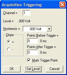
This dialog box allows you to set acquisition trigger conditions (such as level, slope, and number of pre- and post-trigger data points) that define the starting point or “trigger” for data acquisition to disk. Data acquisition to disk will begin only when the trigger (i.e., that point on the waveform in window 0 that corresponds to the level and slope you specified) is detected.
Channel field
Indicates the channel to be triggered. On DI-500 Series instruments, you can choose any enabled channel to trigger from. On all other instruments, this field indicates the lowest-numbered enabled channel. To trigger acquisition from a waveform that is not the lowest numbered channel, you must first move the desired waveform to the lowest numbered channel. See the Variable Waveform Assignments function for assigning any waveform to a specific display window.
Level field
Indicates the current trigger level in volts.
Hysteresis
This field allows you to specify a hysteresis value for reliable triggering on noisy signals. A drop-down list allows you to select one of 16 different values displayed in engineering units.
Slope option buttons
The slope option buttons allow you to define the slope direction (positive- or negative-going) at the acquisition trigger. Selecting the + option button triggers acquisition to start at the trigger level, but only on the waveform’s rising (or positive) slope. Selecting the - option button triggers acquisition to start at the trigger level, but only on the waveform’s falling (or negative) slope.
Points before trigger text box
Allows you to specify the number of data points (and the equivalent amount of time it will take to acquire this many data points at the current sample rate) that will be acquired before the trigger occurs. There is a limit to the amount of pre-trigger data that can be acquired, and it varies with the instrument being used (i.e., plug-in boards or parallel port instrumentation). See also Special Considerations.
Points after trigger text box
Allows you to specify the number of data points (and the equivalent amount of time it will take to acquire this many data points at the current sample rate) that will be acquired after the trigger occurs. There is a limit to the amount of post-trigger data that can be acquired, and it varies with the instrument being used (i.e., plug-in boards or parallel port instrumentation). See also Special Considerations.
Mark Trigger Point check box
When checked, the sample that met the trigger conditions is marked with a vertical line on the WinDaq Acquisition screen. When unchecked, nothing indicates the sample that met the trigger conditions.
OK command button
Allows you to close the Acquisition Triggering dialog box and apply the just configured trigger conditions.
Set Level command button
Allows you to adjust or set the acquisition trigger level. When selected, the Acquisition Triggering dialog box closes and causes the cursor to point to a short horizontal line at the right side of the annotation margin. This short horizontal line is the trigger level indicator.
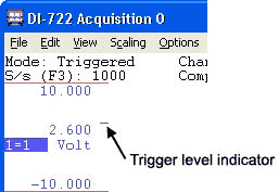
At this point, mouse movement is limited to dragging the trigger level indicator up or down to the desired trigger level. Note that when the mouse is moved, the data display in the left annotation margin changes to indicate trigger level (in volts). When set where desired, clicking the left mouse button sets a new trigger level while clicking the right mouse button retains the existing level.
Cancel command button
Allows you to close the Acquisition Triggering dialog box and cancel any changes made to trigger conditions, provided that the changes were not saved with the OK command button.
Once the trigger level, slope, and number of pre- and post-trigger points is determined, close the Acquisition Triggering dialog box by choosing the OK command button and initiate acquisition to disk in the normal fashion (i.e., assign a file name, specify a file size, and choose Record from the File menu. See Acquire Data to Disk for complete details). In this mode, data acquisition to disk will begin only when a trigger is detected and only the amount of pre- and post-trigger data samples specified will be acquired to disk.
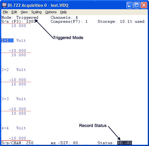
Note that the monitor does not display a waveform until the trigger condition is met. The following illustration shows a typical WinDaq Acquisition screen with acquisition triggering enabled, but no trigger as yet detected. It will remain like this until a trigger condition is detected. Note the Mode: field in the status bar displays Triggered and the Status: field in the bottom annotation line displays RECORD to indicate acquisition triggering is enabled.
When a trigger condition is detected, the sample which met the trigger conditions (the trigger) is marked on the WinDaq Acquisition screen by a vertical line as shown below (if the Mark Trigger Point option is enabled). All points shown to the left of the vertical line (trigger) are the pre-trigger samples and all points shown to the right of the line are post-trigger samples.
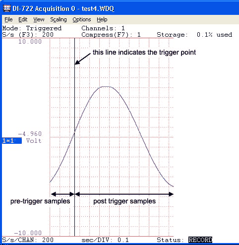
If the screen is not large enough to show all desired pre- and post-trigger samples, only those around the trigger will be displayed, with the ratio of pre to post points the same as that requested in the Acquisition Triggering dialog box.
After storage to disk has started, you must close the file (by choosing Close from the File menu) to exit acquisition triggering mode or to change triggering conditions.
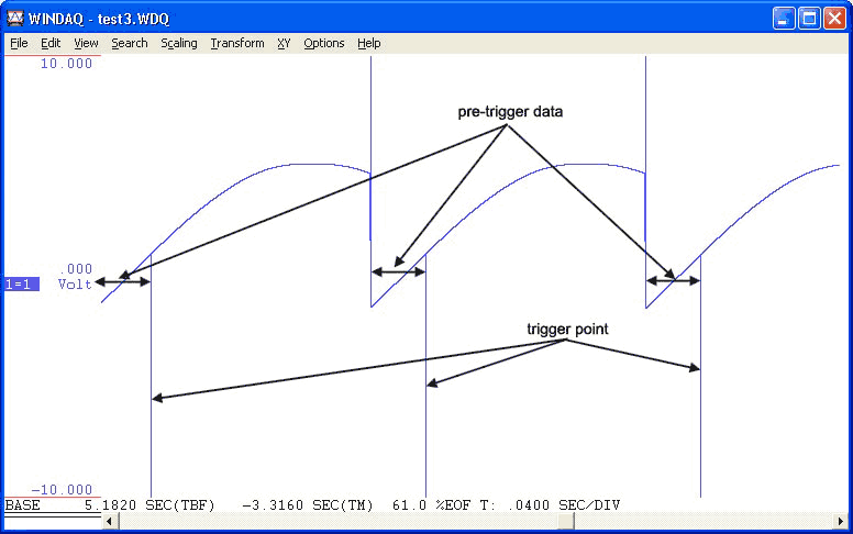
When reviewing the file in WinDaq Waveform Browser playback and analysis software, the start of the pre-trigger data is marked by a positive-going line (from the waveform to the top of the window) and the trigger point is marked by a negative-going line (from the waveform to the bottom of the window).