
Display Mode > Activating Procedure
![]() Click
the Scroll Mode button in the Toolbox.
Click
the Scroll Mode button in the Toolbox.
OR
![]() Click
the Oscilloscope Mode button in the Toolbox.
Click
the Oscilloscope Mode button in the Toolbox.
![]() In
the Options menu click on Scroll Mode or Oscilloscope
Mode….
In
the Options menu click on Scroll Mode or Oscilloscope
Mode….
OR
![]() Double-click
on the Mode:
field in the status bar.
Double-click
on the Mode:
field in the status bar.
![]() Choose
Options Scroll Mode (ALT, O, S) or Options Oscilloscope Mode… (ALT, O,
O).
Choose
Options Scroll Mode (ALT, O, S) or Options Oscilloscope Mode… (ALT, O,
O).
Note that in either display mode, the waveform display can be paused. This allows you to get a stationary look at some point on the waveform. While paused, the Mode: field in the status bar changes from the chosen display mode to Paused. To enable/disable the waveform display pause feature:
![]() In
the Options menu click on Pause Graphics.
In
the Options menu click on Pause Graphics.
![]() Choose
Options Pause Graphics (ALT, O, P).
Choose
Options Pause Graphics (ALT, O, P).
When the pause feature is enabled, a subsequent pause attempt disables the pause feature. The display mode that was active before pausing is restored.
When Oscilloscope Mode… is chosen, the Oscilloscope Triggering dialog box is displayed.
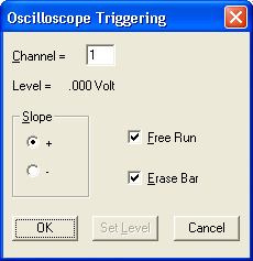
This dialog box allows you to choose between a triggered sweep oscilloscope display or a free-running oscilloscope display. Checking the Free Run check box selects the free running oscilloscope display. Leaving the Free Run check box unchecked selects the triggered sweep oscilloscope display.
If free running is selected, the waveform is displayed constantly on your monitor in a manner identical to an oscilloscope display and the rest of this dialog box can be ignored.
If triggered sweep is selected, you can also set display trigger conditions (such as channel, level, and slope) that define the “trigger” or starting point for displaying the waveform on your monitor. In this mode, the waveform is not displayed until a trigger condition is detected. The waveform will be displayed for a single sweep on your monitor only when a trigger (i.e., that point on the waveform in the selected channel that corresponds to the level and slope specified) is detected. Although it looks similar to the Acquisition Triggering dialog box, this dialog box only sets triggering conditions for the waveform display (not for acquisition to disk).
The triggered sweep display (best used with repetitive waveform signals) allows you to set a level and a slope defining the starting point or “trigger” for the waveform display. The waveform will be sweep-displayed on your screen only when a trigger (i.e., that point on the waveform that corresponds to the level and slope you selected) is detected. This produces a stable display, easily measured or compared with other waveforms since it starts at the same point on the screen with every sweep. This single sweep display will remain on your monitor until the next trigger is detected.
The free-running display allows the waveform signal to “free run” without any triggering conditions. Without triggering conditions to define a starting point, the free-running display updates continuously.
The slope option buttons allow you to select the slope (positive or negative) at which the waveform display will trigger. Selecting the + option button triggers the display to start at the trigger level, but on the waveform’s rising slope. Selecting the - option button triggers the display to start at the trigger level, but on the waveform’s falling slope.
Select the trigger slope.
![]() Clicking
the desired option button. When a slope is selected, a dotted box surrounds
the slope name and a dark dot appears in the slope option button.
Clicking
the desired option button. When a slope is selected, a dotted box surrounds
the slope name and a dark dot appears in the slope option button.
![]() Pressing
the TAB key until one of the two slope options becomes selected. When
selected, a dotted box surrounds the slope name and a dark dot appears
in the slope option button. At this point, the or ¯ cursor control keys
can be used to select the desired slope.
Pressing
the TAB key until one of the two slope options becomes selected. When
selected, a dotted box surrounds the slope name and a dark dot appears
in the slope option button. At this point, the or ¯ cursor control keys
can be used to select the desired slope.
Channel text box
Allows you to specify or select a channel for the trigger source.
Level field
Indicates the current trigger level in volts.
Free Run check box
Allows you to select between a triggered sweep oscilloscope display or a free-running oscilloscope display (see discussion above). Note that this box must be unchecked to set the trigger level.
Erase Bar check box
Allows you to enable/disable the display of the vertical erase bar (cursor) on the waveform. Whether the erase bar is displayed or disabled, the waveform information screen is still “erased” and replaced with a fresh sweep of data.
OK command button
Allows you to close the Oscilloscope Triggering dialog box and apply the just configured display trigger conditions.
Set Level command button
Allows you to adjust or set the trigger level. Note that the Free Run check box must be unchecked to set a trigger level. When selected, the Oscilloscope Triggering dialog box closes and causes the cursor to point to a short horizontal line at the right side of the annotation margin. This short horizontal line is the trigger level indicator.
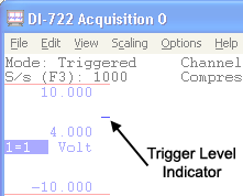
At this point, the mouse is limited to dragging the line up or down to the desired trigger level. Note that when the mouse is moved, the data display in the left annotation margin changes to indicate trigger level (in volts). When set where desired, clicking the left mouse button sets a new trigger level while clicking the right mouse button retains the existing level. Note that if the trigger level is set somewhere above or below the current signal, the signal will disappear from the display.
Cancel command button
Allows you to close the Oscilloscope Triggering dialog box and cancel any changes made to trigger conditions, provided that the changes were not saved with the OK command button.