
|
|
The di_mode function sets trigger parameters for the device. Call di_start_scan to start scanning. Use the di_trigger_status function to check on trigger status. Triggering occurs on the first channel in the input scan list by default but can be designated with scnx. For example, if channel 3 is listed as the first element in the input scan list (in di_inlist), triggering will occur on channel 3 by default.
Note: When triggering occurs, the hardware device starts sending data to the buffer. The hardware device is still sampling data when triggering is off - it is simply not storing it in the buffer. DI-1100, DI-1110, DI-1120, DI-2008, DI-2108, DI-2108-P, DI-4108, DI-4208, and DI-4718B devices only support mode 0.
|
int di_mode(mode); |
|
|
struct di_mode_struct{ |
|
|
unsigned mode:4; |
/* specifies the trigger mode (Unsigned:4) */ |
|
unsigned hystx:4; |
/* specifies the hysteresis index (Unsigned:4)*/ |
|
unsigned scnx:8; |
/* input scan list index of trigger channel (Unsigned:8) */ |
|
unsigned trig_level; |
/* for an analog trigger; specify a 12 or 14-bit, 2’s complement, left justified value. For a digital trigger; specify 1 of the 8 digital input bits. */ |
|
unsigned trig_slope; |
/* 0 triggers on rising slope, 1 triggers on falling slope */ |
|
unsigned trig_pre; |
/* specifies the number of scans through the input list for pre-trigger data */ |
|
unsigned trig_post; |
/* specifies the number of scans through the input list for post-trigger data */ |
|
}*mode; |
|
mode allows you to specify no triggering, single scan triggering, or software triggering. Triggering occurs on the first channel in the input scan list. For example, if channel 3 is listed as the first element in the input scan list, triggering will occur on channel 3.
mode = 0 (no triggering) allows data to be continuously acquired to your buffer the instant di_start_scan is called. Data acquisition does not stop when the buffer is full, the buffer simply gets overwritten.
mode = 1 (for analog trigger signals) and mode = 2 (for digital trigger signals) are single scan trigger modes. The single scan mode is used when it is only necessary to monitor one trigger occurrence. For example: A buffer is allocated, scanning is started, the trigger condition occurs, n pre-trigger data samples and m post-trigger data samples are collected in the buffer (if pre- and/or post-trigger data is desired), and scanning is stopped.
mode = 5 (software triggering) is similar to mode 0 in that data is acquired to your buffer the instant di_start_scan is called, but differs from mode 0 in that you can specify the number of data points that will be acquired. When the buffer contains the desired number of data points, scanning is stopped. This mode is normally used without pre-trigger data. The value entered for trig_post specifies how many data points will be acquired.
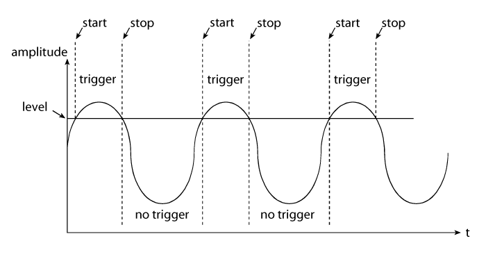
mode = 6 (level triggering) allows data to be acquired to your buffer only when a certain waveform value (specified by trig_level) occurs and then only on the proper slope (specified by trig_slope). For example, assuming a positive slope has been specified, the following illustration shows when data will be acquired to the buffer:

hystx allows you to specify a Hysteresis index that will dictate the hysteresis applied to the trigger level. This is a good approach when dealing with noise. If you have noise near the trigger level and no hysteresis it could cause the trigger condition to toggle on and off rapidly.
| hysteresis index |
hysteresis + and - from level in LSB of 12-bit ADC |
|
| 0 | 0 | |
| 1 | 1 | |
| 2 | 2 | |
| 3 | 3 | |
| 4 | 4 | |
| 5 | 6 | |
| 6 | 9 | |
| 7 | 13 | |
| 8 | 19 | |
| 9 | 28 | |
| 10 | 40 | |
| 11 | 58 | |
| 12 | 84 | |
| 13 | 122 | |
| 14 | 176 | |
| 15 | 255 |
Note: For DI-200, DI-221, and DI-222 instruments use 0 (hystx is not supported).
For example, for a negative slope, if trig_level is 100 and you set hystx to 4, the trigger condition will not occur until the waveform breaks the plane at 96 AND 104. For a positive slope, if trig_level is 100 and you set hystx to 4, the trigger condition will not occur until the waveform breaks the plane at 96 AND 104.
To convert to Volts see Converting Counts to Volts. For example, say you are using a DI-720 USB with a gain setting of one and a trigger level of 5 Volts. Setting hystx to 15 would give us the following formula (using the Simplified formula in Converting Counts to Volts):
Volts = 10*ADReading/32768
Volts = 10*255/32768
Volts = 0.0778
So the Hysteresis Index would allow ±0.0778 volts before triggering (i.e., the waveform must break the plane of both 5.0778 Volts and 4.9222 Volts for trigger condition to occur).
scnx is an input scan list index (pointer) to the trigger channel (0 for the first channel, 1 for the second channel, etc.). It allows you to specify a trigger channel (0 for the first channel). For example, if the channels in your input scan list (set by di_inlist) are (in order) 0, 5, 8, 10, 11 and 20, and you set scnx as 3, 10 would be your trigger channel. If scnx is 5, then 20 would be your trigger channel. The default value is 0 (i.e., the first channel in the input scan list).
trig_level allows you to specify the point at which the trigger occurs. If you wish to trigger on an analog signal, specify a 12-bit, 14-bit, or 16-bit (depending on your instrument’s capability), 2’s complement, left-justified value. See Converting Counts to Volts for correct values. For example, suppose the desired trigger level is 3.5 Volts and your full-scale range is ±10Volts. Using the Simplified formula in Converting Counts to Volts we get:
3.5 = 10* trig_level/32768
trig_level = 11469
If you are triggering on a digital signal, specify one of the eight digital input bits as the trigger according to the following illustration:
| Digital Input Bits: | 0 | 1 | 2 | 3 | 4 | 5 | 6 | 7 |
trig_level value:
|
0 | 2 | 4 | 8 | 16 | 32 | 64 | 128 |
For example, suppose you wanted to trigger on digital input bit 4. You would specify mode.trig_level = 16.
trig_slope allows you to trigger on the rising slope of the analog or digital signal (if trig_slope = 0) or on the falling slope of the analog or digital signal (if trig_slope = 1). The digital signal is 1 if any of the specified digital input bits is high. A transition in the result is required to generate a digital trigger.
trig_pre allows you to specify how many data samples to acquire before the trigger condition occurs. If any amount of pre-trigger information is requested, data is automatically acquired to your buffer when di_start_scan is issued in anticipation of the trigger. If no pre-trigger information is requested (trig_pre = 0), no data is acquired in the buffer until the trigger condition occurs.
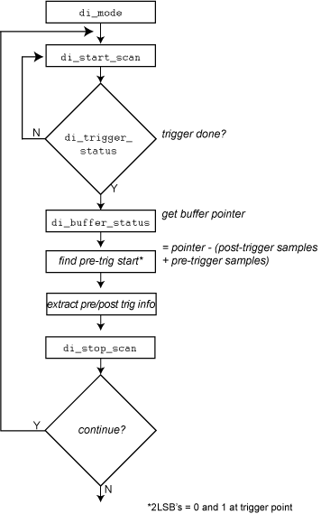
The following flow chart illustrates a typical sequence of function calls required to extract data from the input buffer with pre-trigger data requested.

trig_post allows you to specify how many data samples to acquire after the trigger condition occurs.
This function returns error code.
When in the triggering mode on DI-220, DI-221TC, and DI-222 instruments, the maximum number of samples that can be acquired is 8180 if doing an input operation only or 4090 if doing a simultaneous input/output operation.
Note: If you have a DI-221TC and you wish to perform triggering operations, you can reconfigure your DI-221TC to act like a DI-220, thus allowing triggering operations. This is done by running file DI220.BAT (for hardware with 16 channels or less) or file DI221M.BAT (for hardware with more than 16 channels) during startup instead of DI221.BAT.
When in the triggering mode on DI-400, DI-401, and DI-410 instruments, the maximum number of samples that can be acquired is 15,000 samples, or 8192 if a simultaneous input/output operation is being done.
When in the triggering mode on DI-500, DI-510, DI-720, DI-730, and DI-5001 instruments, the maximum number of samples that can be acquired is 7,500 samples (or 4096 if a simultaneous input/output operation is being done), provided that the sample rate is less than or equal to the maximum communications rate, which is defined by the type of parallel port the instrument is connected to (refer to the di_burst_rate function for complete communications rate details).
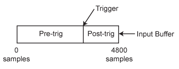
The size of the input buffer you allocate for acquiring the data depends on several factors. At a minimum, this buffer must be large enough to hold the pre- and post-trigger data (if requested) for each element in the input list. For example, suppose we have 16 channels on the input list and we would like to acquire 200 samples of pre-trigger information and 100 samples of post-trigger information. The minimum input buffer size is 16(200+100)
Using the di_buffer_alloc function, you would specify 4800 samples of memory for your input buffer (1 sample = 1 word). Note that the di_buffer_alloc function requires a minimum size of 4096 words for DI-220, DI-221TC, DI-222, DI-400, DI-401, DI-410, DI-500, DI-510, DI-720, DI-730, and DI-5001 instruments.

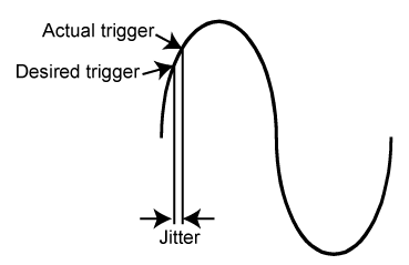
Another special triggering consideration that is common to all instruments is something called jitter. Jitter can be defined as trigger uncertainty.

The maximum amount of jitter can be calculated.

Where:
L= length of the input or output list (whichever is greater)
C0 = the count value of the first element (element 0) in the input scan list (set in di_inlist).
|
#include "200sdk.h" |
|
|
int errcode; |
|
|
struct di_mode_struct mode; |
|
|
char errstr[255]; |
|
|
main() |
|
|
{ |
|
|
int i; |
|
|
if(errcode = di_open()){ |
/* open the device for comm */ |
|
di_strerr(errcode,errstr); |
|
|
printf("%s",errstr); |
|
|
} |
|
|
else |
|
|
printf("Device installed successfully.....\n"); |
|
|
mode.mode = 1; |
/* analog triggering enabled */ |
|
mode.hystx = 0; |
/* reserved for compatibility */ |
|
mode.scnx = 0; |
/* reserved for compatibility */ |
|
mode.trig_level = 0; |
/* trigger on zero crossing */ |
|
mode.trig_slope = 0; |
/* trigger on positive slope */ |
|
mode.trig_pre = 1000; |
/* 1000 pre trigger samples */ |
|
mode.trig_post = 2000; |
/* 2000 post trigger samples */ |
|
if(errcode = di_mode(&mode)){ |
/* initialize mode */ |
|
di_strerr(errcode,errstr); |
|
|
printf("%s",errstr); |
|
|
} |
|
|
di_close(); |
|
|
} |
|
Copyright © DATAQ Instruments, Inc.