
 View Cart
 sales@dataq.com
 330-668-1444
Strain Gage-Based Transducer and Amplifier Selection and Calibration
When choosing a strain gage-based transducer/amplifier combination to acquire data such as force, load, pressure or torque, there are a several important considerations to keep in mind. In addition to measurement range you must consider the sensitivity of the transducer and amplifier as well as the required excitation (supply) voltage.
Once you've chosen an appropriate transducer/amplifier combination and have your DATAQ Instruments data acquisition system up and running, you'll want to display and acquire meaningful units (lbs, psi, etc.). This is accomplished using the calibration features built into WinDaq data acquisition software.
The goal of this application note is to provide you with the knowledge necessary to choose a suitable strain gage-based transducer/amplifier combination and to acquire accurate, meaningful data.
Sensitivity (Gage Factor)
Sensitivity, sometimes referred to as gage factor, is used to determine the output voltage of a transducer with a specified supply (excitation) voltage connected and a physical quantity applied. Multiplying the excitation voltage by the sensitivity yields the full scale output of the transducer (Figure 1).
Figure 1 - With 10V excitation applied and a sensitivity of 3mV/V
The transducer has a maximum full scale output of 30mV (10V * 3mV/V).
The instantaneous output voltage is directly proportional to the physical quantity applied. Take for example a 0-100 psi pressure transducer that requires 10V of excitation and has a sensitivity of 2mV/V. With 100 psi applied, the transducer will output 20mV (the full scale output), with 50 psi applied the transducer will output 10mV (half the full scale output).
Measurement Range
Like strain gage-based transducers, amplifiers also have a sensitivity specification. Ideally the transducer and amplifier will share the same sensitivity allowing you to utilize the full measurement range of your transducer (Figure 2).
Figure 2 - Calculating the sensitivity ratio (R), R = Transducer Sensitivity/Amplifier Sensitivity = 3/3 = 1.
Dividing the full scale measurement range of the transducer by R, 10,000 psi / 1 = 10,000 psi.
Because the transducer and amplifier have the same sensitivity, the amplifier is capable of amplifying the full measurement range of the transducer (10,000 psi).
In cases where the transducer has a higher sensitivity than the amplifier the transducer will be underutilized and the sensitivity ratio will be > 1 (Figure 3).

Figure 3 - Calculating the sensitivity ratio (R), R = Transducer Sensitivity/Amplifier Sensitivity = 3 / 2 = 1.5.
Dividing the full scale measurement range of the transducer by R, 10,000 psi / 1.5 = 6666.67 psi.
Because the transducer has a higher sensitivity, the amplifier cannot amplify the full range (10,000 psi) of the transducer, limiting the full scale measurement range to 6666.67 psi.
It's also important to remember that while a manufacturer may list the sensitivity of a transducer as 2mV/V in a catalog, the actual sensitivity will be listed in the spec. sheet as something like 2.09mv/V or 2.14mV/V. In order to ensure the most accurate measurements these slight offsets must be taken into account during calibration (see Table 1 below). To ensure that the transducer/amplifier combination will accommodate the full range of data that you're attempting to acquire it may be necessary to oversize the transducer (if you're measuring 0-120 psi for example, choose a transducer with a 0-150 psi full scale measurement range).
As you've seen above, it is important that you pay close attention to sensitivity when choosing a non-amplified strain gage-based transducer. Strain gage-based transducers with 2mV/V or 3mV/V sensitivity are ideally suited for DATAQ Instruments strain gage amplifiers (DI-8B38-05, DI-8B38-02).
Calibration
Use the three easy steps outlined in Table 1 to calculate full scale and baseline values to enter into WinDaq.
| Table 1 | ||
| Definitions | Application Example 1 | Application Example 2 |
| ST = Transducer Sensitivity | ST = 2mV/V | ST = 2.14mV/V |
| SM = Amplifier sensitivity | SM = 3mV/V | SM= 3mV/V |
| FT = Full scale of Transducer | FT = 100 psi | FT = 30,000 lbs. |
| Procedure | ||
| 1. Determine R (ST/SM) | R = 2/3 = 0.667 | R = 2.14/3.00 = 0.7133 |
| 2. Determine +Full Scale = (FT/R) | +Full Scale = (100/0.667) = 150 psi | +Full Scale = (30,000/0.7133) = 42,058 lbs. |
| 3. Determine a baseline calibration value. | The transducer will likely output a small voltage even at rest. | There is no load at rest, set low calibration to 0. |
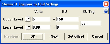
Once you've calculated full scale and baseline values, use the 'EU Settings' features built into WinDaq data acquisition software to display meaningful engineering units.
Using Application Example 1 (Table 1):
- With no pressure applied to the transducer select 'Engineering Unit Settings' from the 'Edit' pull-down menu
- Leave Lower Level, Volts unchanged and enter 0 (zero) in the Low Level, EU box
- Enter 5 in the Upper Level, Volts box and 150 in the Upper Level, EU box
- Change EU Tag to "psi"
- Click 'OK'
WinDaq is now scaled to display engineering units (psi).
Conclusion
To display and acquire accurate, meaningful data using a strain gage-based transducer/amplifier combination it essential that you pay close attention to the sensitivity of both the transducer and amplifier as well as the required supply (excitation) voltage.