Anyone who has connected to the digital outputs of data acquisition or data logger systems (for example the digital outputs of our DI-2108 and Starter Kits) has wrestled with sink and source current specs, and they continue to be a topic of confusion for many. When does sink current matter, and what is it? Same for source current.
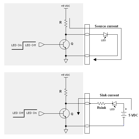
References to sink and source current are made relative to the current switching device inside the system. In most cases, that’s a simple transistor. Source current refers to the ability of the digital output port to supply current. Sink current refers to the ability of the port to receive current. The following figure may help.
In the above, our goal is to light a simple light-emitting diode using the switching ability of a digital output port. The top shows a current source application, and the bottom a current sink approach. Notice the direction of current in both cases: Source supplies current and sink receives current.
When the port supplies (or sources) current it’s limited by the current limiting resistor R. You may or may not be able to draw enough current to light the LED depending upon the LED’s current requirements, but in any event you won’t damage the port. Let’s assume that the LED lights very dimly (or not at all) so that sourcing current is not an option. In other words, the digital port cannot provide (or source) enough current. What can you do?
One option is to provide your own power source that can supply adequate current, use the port to control whether or not the current flows, and thus turn the LED on and off. This configuration is shown at the bottom, of the figure. Now the digital port no longer supplies (sources) current but is configured to receive (or sink) it. To prevent damage to the port you need to be cognizant of its maximum sink current spec. Sinking more than this figure will fry transistor switch Q and render the digital port permanently inoperative. Resistor Rsink provides current limiting when the transistor sinks current.
Now let’s put some meat on this application and assume that the maximum current sink spec for a given digital output port is 10 mA. We ignore any LEDs that require more current than 10 mA and locate one that’s rated for 5 mA and has a forward voltage of 2 V. Ignoring the ON resistance of Q (usually very small), we can calculate Rsink to be (5-2)/0.005 = 600 Ohms to ensure that the port doesn’t sink more than 5 mA, well below its 10 mA maximum rating.
A final point is that the control signal at Q’s base for the current source versus the sink application is inverted. A logical 1 applied to Q’s base in the current source application turns the LED off. A logical 1 turns it on for the current sink application.


 View Cart
 sales@dataq.com
 330-668-1444
12 Comments
vinoth
thanks man….very useful….
Werner Wang
THANKS!
R.M
TNX ,it helped me a lot.
Abhilash
Thanks a lot man..
Abhilash
I do have one question,say that i have a PIC16f886 which by specs has a sinking max output current of 25mA.
Does it mean the same as u have explained because the word Max output current sunk and sourced seems confusing too?
DaqGuy
Your use of the phrase “sinking max output current” is contradictory. Sink means how much current the port an absorb, not what it can supply (source.) So I think you need to look at the specs for your device again, or contact the manufacturer. If it really states the spec as you have described, that’s a typo.
MOHAMED EL TRAMSY
Thanks man….very useful
Paul Land
Great explanation.
Rick Hunt
Sorry about coming late to the party. This is all good basic stuff. I would encourage anyone trying to use the output of a microcontroller to drive anything to use a transistor buffer (2n2222) or a small mosfet to drive the load. If the output specs say 60ma. You need to be well below that. The manufacture’s maximum ratings are the ratings that the device will occur damage.
Tumisang Kelopang
great that was helpful
I have a question
how do we apply these current sources in a PLC i.e IN I/O’S
Daqhelper
Tumisang,
The concept is the same, but the PLC will have it’s own specifications with regard to source and sink current.
Consult the datasheet or contact the PLC manufacturer for additional information.
Regards,
Shawn MacDonald
Application Engineer
DATAQ Instruments Inc.
Anwaruddin Sukamto
Thank you bro..it is usefull