Analog and Digital Data Acquisition using the DI-148/158 and ActiveX
On this Page
Issue
Resolution
Download the AnalogDigitalAcq Sample Program
Enter a DeviceID
Enable, Assign and Display Additional Analog Channels/Digital Bits
Applies To
Issue
You are unable to simultaneously display analog and digital data or toggle individual digital bits using a DI-148/158 and the ActiveX control library.
Resolution
To resolve these issues carefully follow the steps below.
Download the AnalogDigitalAcq Sample Program
Download the AnalogDigitalAcq Visual Basic sample program at: http://www.dataq.com/data-acquisition/software/developer-network/vb6.html.
Enter a DeviceID
Before running the SimAnaDigAcq sample program you must enter a Device ID.
The DeviceID consists of the COM port number that your DI-148/158 is installed onto, the model number (148 or 158) and the baud rate. The format is as follows:

Figure 1 illustrates how/where to enter the DeviceID.

Figure 1
Enter a DeviceID
For further instruction on determining the appropriate DeviceID see "Device Drivers and Device IDs" under "Reference Materials" in the ActiveX help file. You can download the latest ActiveX help file at www.dataq.com/support/documentation/helpfiles/index.htm.
Enable, Assign and Display Additional Analog Channels/Digital Bits
- Add Additional Analog Channels (for the purpose of this example we'll add analog channel two):
- Begin by adding channel two to the ChannelList as shown in Figure 2.

Figure 2
Add channel two to ChannelList Note — channel two on your DI-148/158 corresponds to channel one in the ChannelList property (channel one on your DI-148/158 corresponds to zero). - Choose the object view and double-click DQChart on the VB toolbar (Figure 3). Resize and relocate the chart as you wish.
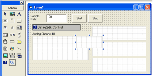
Figure 3
Double-click DQChart in the toolbar to add a chart to the form - Set the DQChart Channel property to 2 in order to display channel two data (Figure 4).
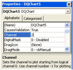
Figure 4
Set the DQChart channel property to 2 - With the chart placed in the form and the Channel property set, add the DQChart to the chart list as shown in Figure 5.

Figure 5
Add the DQChart to the chart list - Edit the DataqSdk1.ADChannelCount property to reflect the total number of channels enabled (Figure 6).
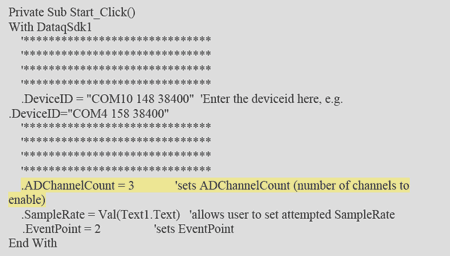
Figure 6
Edit the ADChannelCount property
- Begin by adding channel two to the ChannelList as shown in Figure 2.
- Add Additional Digital Bits (for the purpose of this example we'll add digital bit 3):
- Choose the object view and double-click DQChart on the VB toolbar (Figure 7). Resize and relocate the chart as you wish.
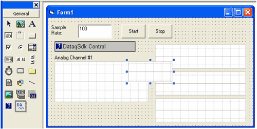
Figure 7
Double-click DQChart in the toolbar to add a chart to the form - Set the DQChart Channel property to 0 (zero) and the DQChart DigitalMask property to 2048 - PlotBit11 (Figure 8)
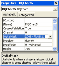
Figure 8
Set the DQChart DigitalMask property to 2048 — PlotBit11 - With the chart placed in the form and the Channel and DigitalMask properties set, add the DQChart to the chart list as shown in Figure 9.

Figure 9
Add the DQChart to the chart list
- Choose the object view and double-click DQChart on the VB toolbar (Figure 7). Resize and relocate the chart as you wish.
- Set the Direction of the Digital Bits
Before individual bits can be toggled the direction of the digital bits must be set.
The DigitalDir constant is used to set the direction of the digital bits (as outputs). This is accomplished by setting the DataqSdk1.DigitalOutput property equal to the DigitalDir constant. Individual bits can be set as inputs on the same line (Figure 10).
Figure 10
Set the direction of the digital bits - Toggle Individual Bits (outputs only)
With the direction of the digital bits set individual bits can be toggled as shown in Figure 11. Each digital port assigned to DataqSdk1.DigitalOutput will output a 1 (high).
Figure 11
Toggle individual bits
Applies To
The DI-148/158 and AnalogDigitalAcq sample program.


 View Cart
 sales@dataq.com
 330-668-1444