
 View Cart
 sales@dataq.com
 330-668-1444
Model DI-5B42-01
Isolated 4-20mA 5B-style Amplifier
Stock
- Isolated +20VDC Current Loop Supply
- Provides Isolation For Non-Isolated 2-Wire Transmitters
- High Level Voltage Output: +1V to +5V
- 1500Vrms Transformer Isolation
- ANSI/IEEE C37.90.1-1989 Transient Protection
- Input Protected to 240VAC Continuous
- 100dB CMR
- 100Hz Signal Bandwidth
- ±0.05% Accuracy
- ±0.02% Linearity
- CSA Certified
- View Dimensions and pinout
 Share
Share
Description
Each DI-5B42 2-wire transmitter interface module provides a single channel which accepts a 4 to 20 mA process current input and provides a standard +1 to +5V output signal (see block diagram). An isolated +20VDC regulated power supply is provided to power the current transmitter. This allows a 2-wire loop powered transmitter to be directly connected to the DI-5B42 without requiring an external power supply. The regulated supply will provide a nominal +20VDC at a loop current of 4mA to 20mA.
The DI-5B42 will provide a 1500V isolation barrier for non-isolated 2-wire field transmitters. It can also be used when additional isolation is required between an isolated 2-wire transmitter and the input stage of the control room computer. The voltage output is logic switch controlled, which allows these modules to share a common analog bus without the requirement of external multiplexers.
The DI-5B modules are designed with a completely isolated computer side circuit which can be floated to ±50V from Power Common, pin 16. This complete isolation means that no connection is required between I/O Common and Power Common for proper operation of the output switch. If desired, the output switch can be turned on continuously by simply connecting pin 22, the Read-Enable pin to I/O Common, pin 19.
A precision 20Ω current conversion resistor is supplied with the module. All field inputs are fully protected from accidental connection of power-line voltages up to 240VAC. The module has a 3dB bandwidth of 100Hz.
Signal filtering is accomplished with a six-pole filter, with two poles on the field side of the isolation barrier, and the other four on the computer side.
Accessories
Description
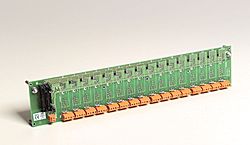
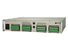
16-channel backplane for 5B modules. Each module has its own analog bus. For use with DI-5B Modules.
Description
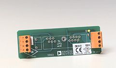
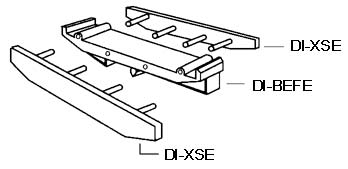
Base element with snap foot required for use with models DI-5B03 and DI-5B04 Backplanes. For use with DI-5B Modules.
Description
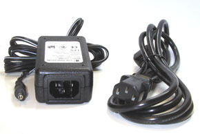
5V DC Power Supply for use with both DI-5B and DI-8B Backplanes.
Description
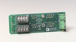
Side element required for use with models DI-5B03 and DI-5B04 Backplanes. For use with DI-5B Modules and Backplanes.
Specifications
| Input Range: | 4mA to 20mA |
| Input Resistor: | Value: 20.00Ω Accuracy: ±0.1% Stability: ±10ppm/ºC |
| Loop Supply Voltage: | Nominal 20V at 4mA to 20mA |
| Isolated Excitation Protection: | Continuous: 240Vrms max Transient: ANSI/IEEE C37.90.1-1989 |
| Input Protection: | Continuous: 240Vrms max Transient: ANSI/IEEE C37.90.1-1989 |
| CMV, Input to Output: | Continuous: 1500Vrms max Transient: ANSI/IEEE C37.90.1-1989 |
| CMR (50Hz or 60Hz): | 100dB |
| NMR: | 120dB per Decade above 100Hz |
| Accuracy: | ±0.05% Span ±4µA RTI (Includes nonlinearity, hysteresis and repeatability; RTI=Referenced to input; VZ is the input voltage that results in 0V output.) |
| Nonlinearity: | ±0.02% Span |
| Stability: | Input Offset: ±1µV/°C Output Offset: ±40µV/°C Gain: ±25ppm/°C of reading |
| Noise: | Input, 0.1 to 10Hz: 10nArms Output, 100kHz: 500µVrms |
| Bandwidth, -3dB: | 100Hz |
| Response Time, 90% Span: | 4ms |
| Output Range: | +1V to +5V |
| Output Resistance: | 50Ω |
| Output Protection: | Continuous Short to Ground |
| Output Selection Time: (to ±1mV of Vout) |
6µs at Cload = 0 to 2000pF |
| Output Current Limit: | ±20mA max |
| Output Enable Control: | Max Logic “0”: +0.8V Min Logic “1”: +2.4V Max Logic “1”: +36V Input Current, “0”, “1”: 0.5µA |
| Power Supply Voltage: | +5VDC ±5% |
| Power Supply Current: | 180mA at load of 20mA 100mA at load of 4mA |
| Power Supply Sensitivity: | ±10µV/% RTI (RTI=Referenced to input.) |
| Mechanical Dimensions: | 2.28" × 2.26" × 0.60" (58mm × 57mm × 15mm) |
| Operating Temperature: | -40ºC to +85ºC |
| Storage Temperature: | -40ºC to +85ºC |
| Relative Humidity: | 0 to 95% Noncondensing |
| RFI Susceptibility: | ±0.5% Span Error at 400MHz, 5W, 3ft |
Articles
Bandwidth Considerations for DI-5B and DI-8B Signal Conditioning Modules
Learn the Importance of Isolation In Four Easy Lessons
How To Calibrate Strain Gage-Based Transducers Using DI-5B38 Strain Amplifiers
Other Products in the Series
none