
 View Cart
 sales@dataq.com
 330-668-1444
WinDaq Add-on Programable Digital and Alarm Outputs
Digital Alarm Output provides programable and manual digital control for closed-loop applications. Currently, only instruments running on USB mode support this feature. For example, DI-4108-E supports both USB and Ethernet modes, but you can only use this addon when DI-4108-E is running on USB mode.
Operation
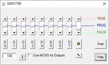
- Use button D0...D7 to enter the logical equation for the corresponding digital output
- Lower DIO channels on DI-2108/4208/4208/2008 are reserved as input by WinDaq as Event, Record, Rate and Counter channel, to use them, check Use All DIO for Outputs option. By choosing this option, all can be changed to outputs. If some of the input functions are needed in WinDaq, set the Dout to TRUE manually and you can send the digital signal to the port. For example, manually set D3 to TRUE, you can use D3 as counter channel in WinDaq
- If you wish to use Digital Inputs, Event, Rate or Counter inputs after you are done with the control, please either recycle the power on the instrument or manually set all DIO to TRUE before you exit this add on to reset the direction for all DIOs. WinDaq will not initialize the direction of the port.
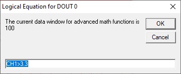
- Data Window Size determines the number of data points when evaluating MIN, MAX, AVE, RMS and ACRMS
- Slides has three states. It controls the state of a corresponding output
- TRUE: assign TRUE unconditionally
- FALSE: assign FALSE state unconditionally
- PROG: Set the output to TRUE if the logical expression for the corresponding channel renders TRUE
- Please click here to learn how to configurate the basic math equation. Besides basic math, following extra control are available
- The syntax has three parts, separated by comma ","
- Optional first part address how long the delay should be before the logical expression is evaluated, and its syntax is DELAY n, where n is number of seconds to delay. For example, DELAY 100
- Second part is the standard logical expression. For example, CH1*CH2>10
- Optional third part is if further comparison should be conducted, and its syntax is HOLD if the answer is no. In this mode, the trigger waits for the change from the initial state of the logical expression, for example, we use CH3>1, HOLD as the expression
- If CH3 is lower than 1 when the the addon is started, it waits until CH3 is higher than 1 before entering the HOLD state
- If CH3 is higher than 1 when the the addon is started, it waits until CH3 is lower than 1 before entering the HOLD state
- Here are some examples
- CH3>1: This is just the standard logical expression, without the optional part 1 nor part 3
- DELAY 20, CH3>1: Do nothing for 20 seconds, then perform the comparison and output to Dx based on the result. Without the optional part 3
- CH3>1, HOLD: Once the reading on CH3 changes, the output will remain unchanged. Without the optional part 1
- DELAY 20, CH3>1, HOLD, all three parts are present
- Limitations
- Not every data point is tested against the trigger condition, a compromise is to use data-window derived results, such as MIN, MAX, AVE, RMS and ACRMS . The add-on is paced by Windows' timer, up to 50Hz.
- When ChannelStretch is used, D0-6 appears in the first instrument only