
 View Cart
 sales@dataq.com
 330-668-1444
Suppose you’re browsing the DATAQ web site looking for a DI-8B series, analog voltage module to acquire a 10V peak-to-peak, 100Hz waveform. You come across the DI-8B31-02. It’s an analog voltage module; it has a full scale measurement range of ±5V, perfect. Not so fast! The DI-8B31-02 has a bandwidth of 3Hz. What does that mean? It means that sub-3 Hz frequencies will be displayed correctly, while any component of the waveform with a frequency approaching 3Hz will begin to lose amplitude or get smaller (attenuate). As a result, your 10V peak-to-peak, 100Hz signal will look something like this:
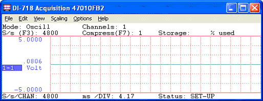
As you can see, the amplitude of the 100Hz waveform has attenuated to nothing and the data is useless.
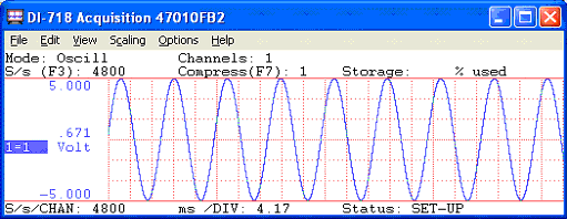
Below, the same signal is acquired using a DI-8B41-02 module with a bandwidth of 1 kHz.
To further illustrate this point, let’s look at a real-life application where bandwidth became an issue.
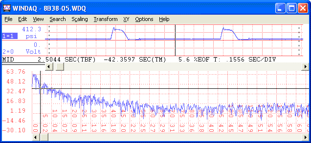
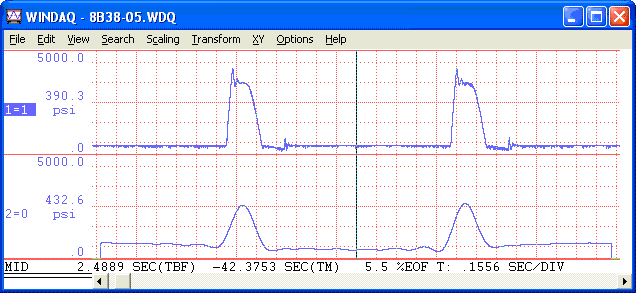
For years a customer of ours had been using DI-8B38-05 modules (with a bandwidth of 8 kHz) to acquire data from strain-gage based pressure transducers. In a pinch, needing to acquire an additional channel, the customer substituted a DI-8B38-32 (with a bandwidth of 3Hz). The resulting waveforms are displayed below.
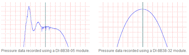
As you can clearly see, any component above 3 Hz is non-existent on the channel containing the DI-8B38-32. It just so happened that these high frequency changes were essential to the customer’s analysis and so the data were useless.
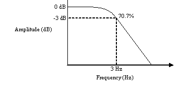
This outcome is the result of the bandwidth limitation of the DI-8B38-32 whereby the amplitude of the signal gradually attenuates to 70.7% (-3 dB) as the frequency approaches 3Hz. As shown in the plot below, amplitude will attenuate more and more as the frequency continues to rise beyond the bandwidth of the module.
This is easily verified by applying a low-pass filter to the waveform generated using the DI-8B38-05 module.
We’ll begin by performing a Fast Fourier Transform (FFT):
Next, we’ll apply the low pass filter (at 3Hz):
Finally, we’ll perform an Inverse Transform:
Follow Us![]()
![]()
![]()
![]()
![]()
![]()
![]()
![]()