
 View Cart
 sales@dataq.com
 330-668-1444
Note: The DI-740 mentioned below is now obsolete. Consider instead the DI-808 or DI-2008. Both the DI-808 and DI-2008 include a 15VDC excitation supply, feature eight differential and isolated analog input channels, and programmable measurement ranges up to ±50V full scale.
It’s a critical constraint that demands a critical measurement: Your control signal says “NOW!” to a hydraulic actuator. How long does it take for the actuator first to start moving, then to fully engage? Our customer constantly asks this question during the maintenance and qualification of their hydraulically driven process used in the manufacture of cast iron pipe. Chart recorders couldn’t provide the amplitude or time resolution required for the measurement. Other data acquisition products were either too slow, or unwieldy in their implementation. Since this is a complex measurement requiring simultaneous measurements of pressure, control and distance (of actuator travel), our DI-740 was the perfect choice.
The DI-740 is connected to four signals: Two 4-20mA process current output pressure transducers, one actuator control signal, and one LVDT connected to the hydraulic actuator and used to measure actuator displacement. The DI-740 provides excitation for the two pressure transducers, thus eliminating the need for extra power supplies. WinDaq software is used to provide real time display and stream-to-disk recording of the measured waveforms. WinDaq software is the perfect complement to the application since speed is an essential ingredient for the measurement. Properly functioning hydraulic actuators fully engage in less 20ms so a high sample rate per channel must be maintained to provide adequate time resolution. In this application, WinDaq software maintained a simultaneous display and throughput to disk rate of 10,000 samples per second.
Figure 1 is a fully compressed view of a 3MB data file generated at the customer’s facility using WinDaq Waveform Browser software. It shows two pressure waveforms (annotated as “Rod” and “Blind End”), an LVDT signal produced by actuator movement (“LVDT Feedback”), and a control signal used to engage the actuator (“Output to Valve”). The pressure waveforms are calibrated in units of PISG, but the actuator movement and control signals are left in units of “VOLTS” since only time measurements are critical. The circled area indicates our area of interest, where our customer determines actuator response.
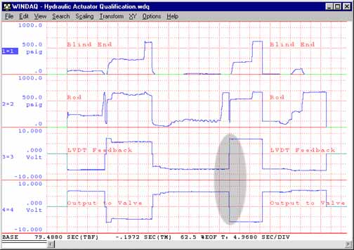
Figure 1 — A fully compressed view of a 3MB recording of hydraulic pressure and actuator signals.
Figure 2 is a time-expanded view of our area of interest. At this time resolution, the slope of the LVDT Feedback signal is clearly visible and easily compared to the control signal. Job one is to determine how long it takes for the actuator to respond to the control signal. As measured by WinDaq Waveform Browser software using its built-in cursor and time marker and indicated by “A”, the result was 1.2ms. Finally, the elapsed time taken by the actuator to fully engage is determined (“B”). Again, using WinDaq‘s built-in time measurement tools, that time was determined to be 15.6ms. Based on this information, the hydraulic valve passed inspection.
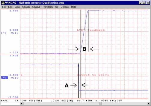
Figure 2 — Expanded area of interest clearly showing the valve’s slower reaction (“LVDT Feedback”) in response to the actuator signal (“Output to Valve”).
Finally, Figure 3 shows the result of a calculated channel (Valve Velocity) using Advanced CODAS software. Ideally, the actuator should smoothly engage during its transition from closed to open. The dimple at the top of the calculated velocity channel, however, shows that the actuator briefly hesitates halfway through the transition. This was a surprising, but not disqualifying characteristic.
Speed, compactness, and flexibility define the use of the DI-740 in this application where events transpire in milliseconds, and a variety of signal types are measured. As such, it’s an excellent example of how DATAQ Instruments equipment is applied in demanding and unusual situations to solve both common and unusual problems.
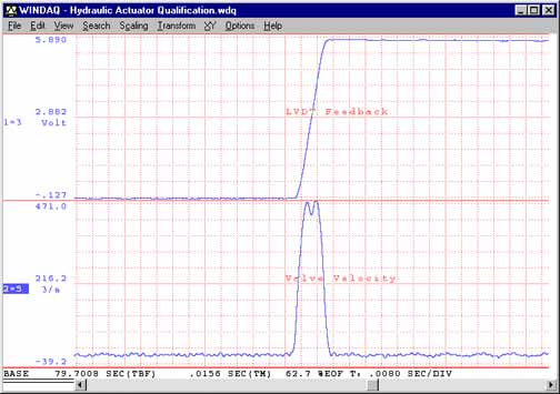
Figure 3 — The “Valve Velocity” channel calculated by Advanced CODAS software shows an unanticipated hesitation in the rate of change of the actuator as it transitions from its closed to open position.
Follow Us![]()
![]()
![]()
![]()
![]()
![]()
![]()
![]()