
 View Cart
 sales@dataq.com
 330-668-1444
The Art and Science of Reliability
John Deere is a major supplier of agriculture, construction, forestry, consumer, and commercial equipment with a reputation for quality and innovation. At the company's Construction and Forestry Division in Dubuque, IA, engineers are deploying cutting-edge technology to ensure utmost product performance and reliability. Vital to this effort is the division's data acquisition program that allows actual field measurements to be combined and compared with design models. This melding of theory and fact leads to better insights and more efficient designs and allows John Deere to reach the market faster with better products.
John Deere's program covers practically every aspect of industrial data acquisition with measurements taken from three primary equipment systems: structure, power train, and hydraulics. Within these categories, the engineers measure a vast array of parameters. They combine in- house expertise with off-the-shelf products to create appropriate data acquisition solutions. To meet the data acquisition hardware/software and signal-conditioning requirements, the company uses products from DATAQ Instruments. John Deere engineers integrate these products with transducers and packaging suitable for the punishing environments where they will be used. They also combine in-house setup and translation programs with commercial analysis software to yield optimal final results.
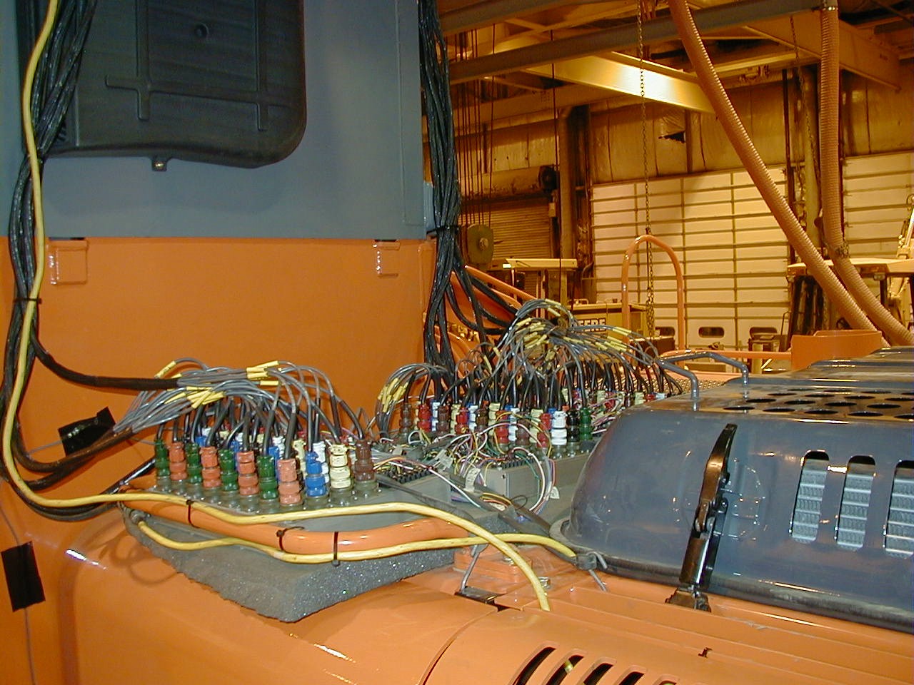
Typical Cabling Implementation for a 96-channel Application
Click on image for close-up
Signal Types
Many of the variables that must be acquired and pooled to construct an accurate picture of a complex mechanical system like an 11 ton backhoe or a 90 ton excavator during operation are listed in Table 1 (below). In a large backhoe, for example, tension and compression stresses place an enormous load on the structure, defining the need to measure hydraulic pressures, flows, and temperatures. The heart of the equipment-the engine and power train-demands accurate measurements of torque, horsepower, temperatures, and pressures. Depending upon the goal of a given test, the engineers could measure as few as 16 or as many as 256 channels of these signal types in any combination, but typical applications rarely exceed a channel count of 128.
| Table 1: Range of Signal Types Measured by John Deere Engineers | ||||
| Source(s) | Parameter | Transducer Type | Typical Measurement Span | Typical Transducer Outputs |
| Engine/Hydraulics | Pressure | Strain-Gage Based Pressure Sensor | Vacuum to 10,000 psi | 3 mV/V |
| Temperature | RTD, Thermocouple | -40 to 1,000°C | mV | |
| Flow | Positive Displacement or Vane Type Flow Meter with Magnetic Pickup | 0 to 300 Gallons/Hour | Pulse Train | |
| Frame/Structural | Stress | Strain Gage | ±50 to ±6,000 μstrain | μVmV |
| Vibration | Strain Gage Accelerometer Piezoresistive | ±20g | mV | |
| Rotation | Angle Encoder | 0 to 360° (Unlimited 360° Repetitions) | V | |
| DisplacementRotation | LVDT, String Pot, DCDT, RTDT | 0 to a Few Millimeters 0 to 8 Feet | VmV | |
| Power Train | Tractive Load or Force | Load Cell | 0 to 50 lb; 0 to 250,000 lb | 3 mV/V |
| Torque | Gauged Shaft in Torque Configuration | 0 to 500 ft-lb | mV | |
| rpm | Magnetic Pickup | <20 rpm (Crawler Tracks); 120,000 rpm (Turbochargers) | Pulse Train | |
Signal Conditioning
The wide range of measured signal types and levels requires signal conditioners that are flexible and modular. Since as many as 256 channels can be acquired at a time for one test, and John Deere maintains dozens of test systems that can run in parallel, low cost also is important.
John Deere selected DATAQ's 5B-style amplifiers, described as rugged, hockey puck-like devices that plug into a data acquisition backplane. Each of the nearly 100 amplifiers in this line measures a specific function over a fixed range so one is used for each channel. The modules can be mixed and matched in any combination to conform to the requirements of a given application.
In addition, the amplifiers provide built-in input-to-output isolation, which is crucial when measurements are taken from disparate sources on a massive vehicle. Ground in a situation like that always is a relative term, with a high probability of differences in ground potential.
The isolation barrier allows the front end of an amplifier to float relative to those of other amplifiers. As a result, the inevitable presence of common-mode voltages will not damage the data acquisition system, and accurate measurements will be reliably made in spite of them.
Ethernet Data Acquisition
The backplane with 32 channels of signal conditioning is packaged in the same enclosure as the data acquisition hardware. The front end features a delta-sigma ADC per channel with anti-alias filtering and simultaneous conversions to facilitate the eventual analysis of structure-related stress and vibration waveforms.
Each enclosure provides a programmable total sample throughput rate ranging from 200 Hz to 320,000 Hz. Measurement resolution is 16 bits, and all acquired data is delivered to an integral 100Base-T Ethernet interface, one per enclosure, that allows multiple enclosures to be daisychained using standard CAT-5 cable for higher channel counts.
Moreover, data acquired from all channels across multiple enclosures is fully synchronous. For example, four daisy-chained enclosures can yield a total data throughput rate of as much as 1,280,000 S/s, and each sample period is fully synchronized across 128 channels. Finally, all information is delivered in real time to the Ethernet interface of a cab-mounted laptop PC running WinDaq data acquisition software (Figure 1).
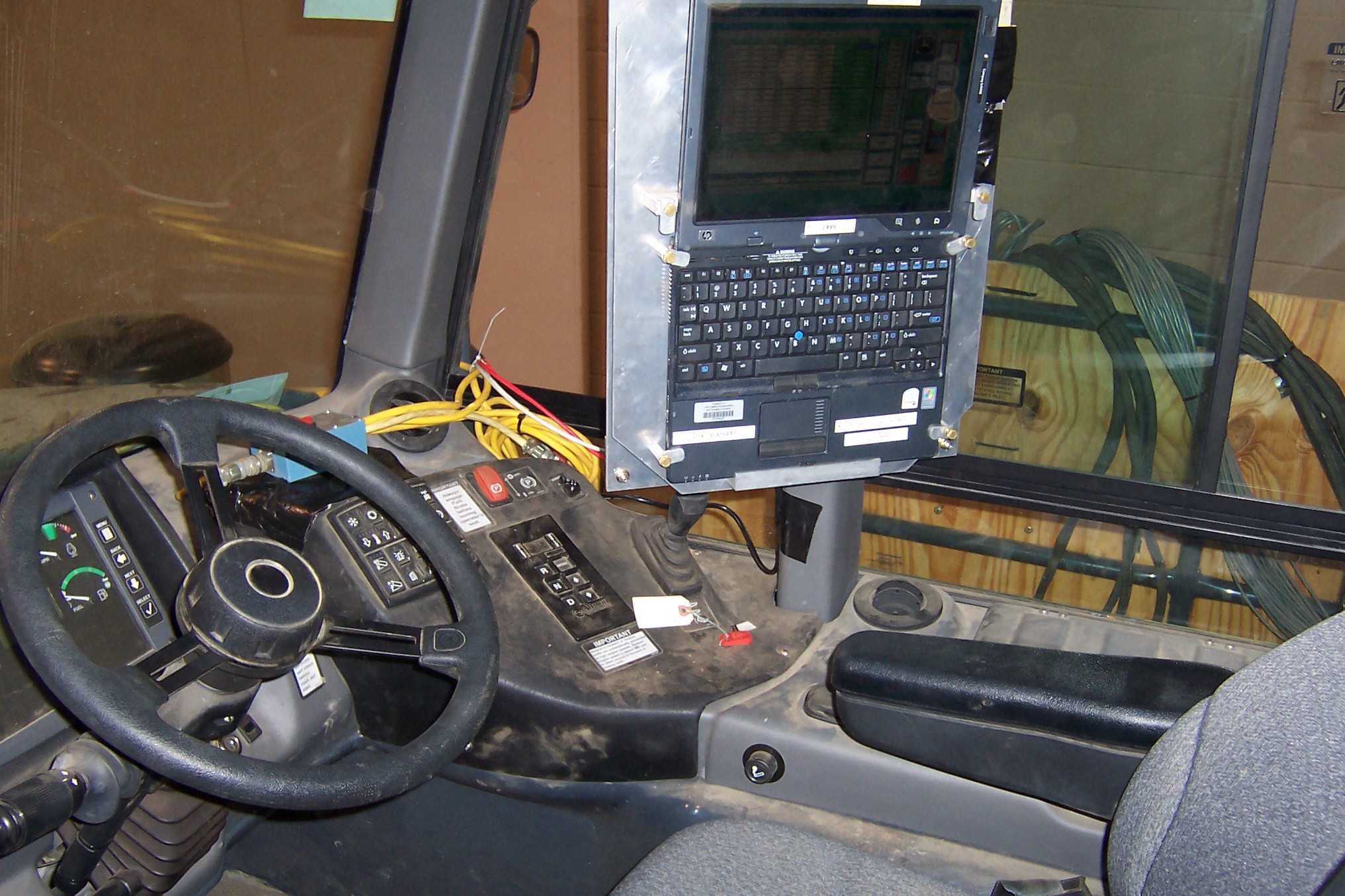
Figure 1
Cab-Mounted Off-the-Shelf Laptop PC Providing Real-Time Feedback for Acquired Signals
Click on image for close-up
The John Deere engineers chose an Ethernet approach that provides hardware synchronization via two unused CAT-5 cable pairs. One pair carries a master 16-MHz clock and the second a trigger signal. The clock is daisy-chained between units, and each unit incorporates a phase-locked loop (PLL) that provides failsafe operation and exactly reproduces the master clock with zero phase delay (Figure 2).
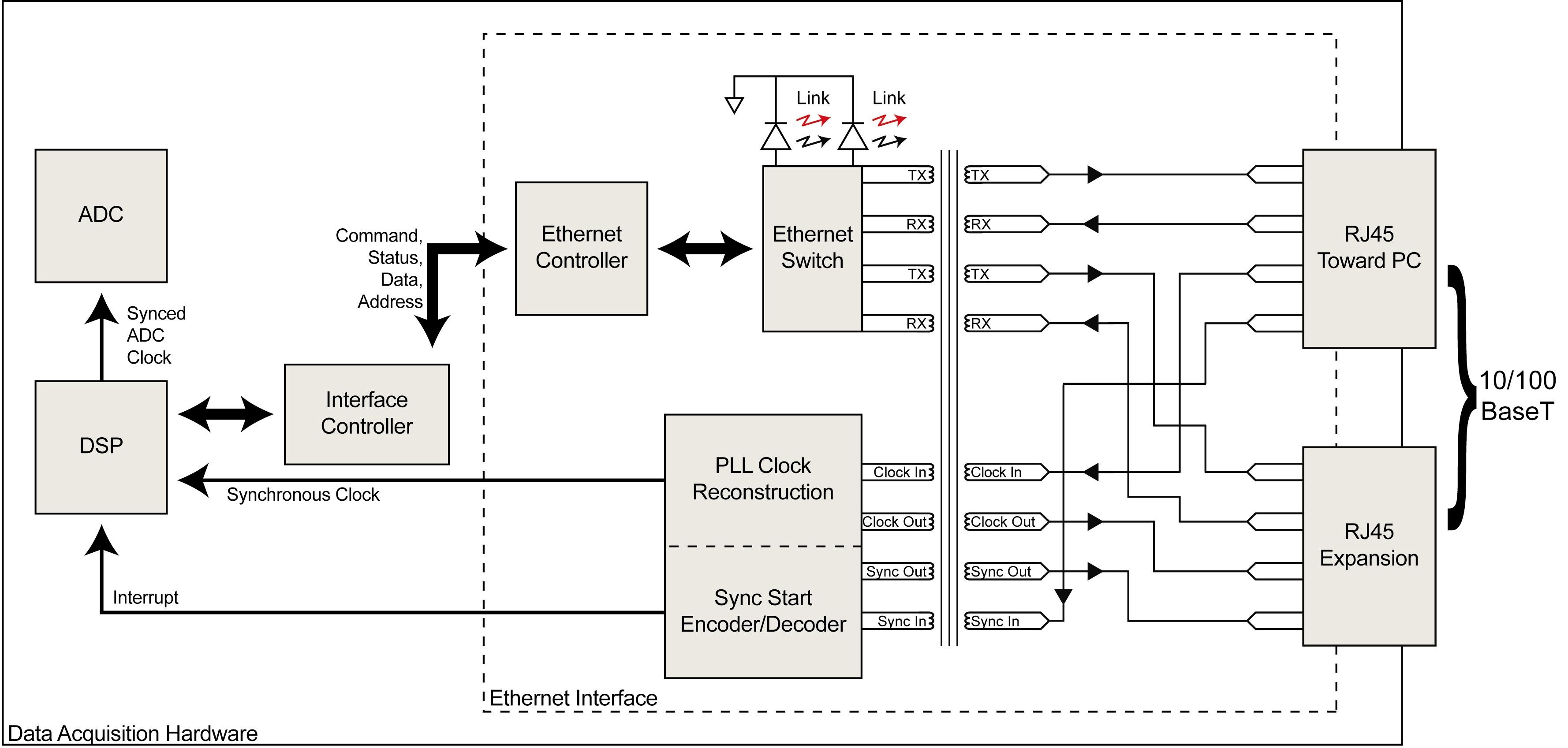
Figure 2
Architecture and Typical Interconnect of Data Acquisition Devices Supporting Synchronous Ethernet Technology
Click on image for close-up
The failsafe feature is a unique aspect of the PLL that ensures the lock is maintained in the event of momentary or even longer-term interruptions in the daisy-chained master clock, subject only to thermal drift. By incorporating PLLs into each data acquisition unit, they remain precisely synced to the master clock in frequency as well as phase, guaranteeing synchronous analog-to-digital conversions among individual units and between individual channels. The addition of a master trigger signal on the second CAT-5 cable pair completes the picture to ensure that all units in the distributed chain initiate sampling at the same instant.
The synchronous Ethernet interface solves many problems:
- It leverages a ubiquitous standard. The Ethernet interface is found everywhere and precisely defines the connectors and interconnecting cables that the standard uses.
- It supports modularity and expansion. Enclosures can be easily swapped, added, or removed to increase or decrease channel count as the application requires.
- Full channel synchronization is crucial for subsequent frame stress analysis. For example, data points acquired on channel one in enclosure one fall in precisely the same time slot as data points acquired on channel 256 in enclosure eight.
- Ethernet is a standard with inherent isolation. Data communications reliability is bulletproof even in the presence of common-mode voltages.
- The communications cable lengths are virtually unlimited. Ethernet intrinsically allows distances as great as 100 meters between switches and hubs. Since the data acquisition system's synchronous interface provides a built-in Ethernet switch, the distance between individual enclosures and between them and the PC can be as long as 100 meters, more than enough to instrument even the largest John Deere equipment.
Why Not LXI?
Officially released in September 2005, LAN eXtensions for Instrumentation (LXI) is destined to provide a contemporary alternative to the aged GPIB (IEEE-488) standard. Built on top of prolific Ethernet, it seems on the surface that LXI has the capacity to be applied to the John Deere application. However, a closer look at the standard reveals a number of weaknesses that preclude its use. The problem is the latency and drift inherent with its synchronizing approaches. LXI defines three trigger mechanisms that can be used for multi-box synchronization, a LAN-based approach (Class C), one based on the IEEE-1588 Precision Time Protocol (Class B), and a third based on a daisy chain or star-connected Trigger Bus (Class A).
A LAN trigger, available on all LXI instrument classes, initiates timing under program control. Although the simplest to implement, this approach suffers from unpredictable latencies that are a function of the initiating program, as well as the LAN itself, rendering this approach wholly unsuitable for the tight synchronous data acquisition requirements of Deere’s application.
Class B LXI devices incorporate an IEEE-1588 timing mechanism that achieves multiple device synchronization over the LXI local area network. LXI devices that support 1588 incorporate special hardware between the device’s MAC and PHY to detect uniquely encoded 1588 packets. This approach provides considerable latency improvement versus LAN triggers, but timing uncertainty is still subject to LAN latency and also dependent upon the specific LXI device, yielding total latency in the unpredictable range of tens of nanoseconds to tens of microseconds. Further, since individual LXI device clocks operate asynchronously 1588 packets would need to consume considerable LAN bandwidth to maintain any hope of in-phase operation to satisfy Deere’s synchronous data acquisition requirements, and the LXI standard provides no guidance for such operation.
Class A LXI devices augment 1588 with a separately cabled Trigger Bus that carries synchronizing signals to multiple LXI devices in a daisy chain or star connection fashion. This approach removes LAN latencies from consideration, improving trigger accuracy as a result, but still suffers from a lack of LXI Standard guidance as to how multi-unit and multi-channel synchronization can be maintained at the continuous, high-speed conversion rates of the Deere application. Furthermore, since LXI is a relatively new standard, and vendors have chosen to get their feet wet with Class C designs, there is a dearth of Class A instruments, especially those that support Deere’s high speed requirements.
Further complicating the LXI approach is cabling. Although LXI represents a major step forward compared to its GPIB forerunner, it failed to simplify cabling between devices. In fact, since GPIB supported a daisy-chain approach between instruments, LXI takes a step backward requiring that individual units cable back to a central Ethernet hub or switch. Add to this the need for a secondary cable for a Trigger Bus between units to have any hope for unit synchronization and the LXI approach begins to look complicated, problematic, and expensive for the Deere application. The upshot is that 1588 enhancements to LXI are intended as an accurate means to time stamp, event mark, and initiate processes, not necessarily as a continuous, long-term, high-speed, and distributed multi-channel synchronizing mechanism.
The Ethernet approach chosen by Deere engineers solves these problems by incorporating a synchronizing mechanism that is built into two unused CAT-5 cable pairs. One pair carries a master 16 MHz clock, and the second carries a trigger signal. The clock is daisy-chained between units, and each unit incorporates a phase lock loop (PLL) that provides failsafe operation and exactly reproduces the master clock with zero phase delay. The failsafe feature is a unique aspect of the PLL that ensures that lock is maintained (subject only to thermal drift) in the event of momentary, or even longer-term interruptions in the daisy-chained master clock. The incorporation of PLLs into each data acquisition unit ensures that they remain precisely synced to the master clock in frequency as well as phase, thereby guaranteeing synchronous analog to digital conversions between individual units and between individual channels. The addition of a master trigger signal on the second CAT-5 cable pair completes the picture to ensure that all units in the distributed chain initiate sampling at the same instant, unencumbered by LAN latencies.
Data Acquisition and Analysis Software
John Deere engineers assembled a complementary collection of off-the-shelf and custom software to quickly move the measurement projects from initial setup to final results. A maximum count of 256 channels means that an efficient approach to swiftly configure and reconfigure tests was mandatory. The setup program developed by John Deere accepts inputs such as channel selection, engineering unit scaling constants and tags, and sample rate and creates a setup file for each data acquisition enclosure.
The file assumes the same filename and format as the default configuration file used by WinDaq, enabling the configuration defined by the test engineers upon power-up without further manipulation. The software synchronously acquires channel data across multiple enclosures, produces a real-time graphical display in calibrated units on the display of the cab-mounted PC's display, and streams all the data to the PC's disk for a permanent record.
Following data acquisition, attention is turned to analysis where engineers use a software suite from nCode. This process is augmented by another in-house program that seamlessly converts acquired data files into nCode's format and performs turnkey analysis at the same time.
The range of signals accumulated during data acquisition is split into two analysis paths. Stress and vibration signals from the equipment's frame and structure are applied to nCode's nSoft suite of analysis software, which is optimized for fatigue analysis.
From it, John Deere engineers derive predictive failure analyses that feed their design qualification assessments. This life testing aspect is a major component that drives company quality programs and, ultimately, equipment reliability and customer satisfaction.
Signals from the engine and power train take a different analysis path through another nCode application called Glyphworks. Raw data values are subjected to a suite of advanced mathematical functions and reduced to min/max values and histogram outputs for evaluation. These results merge with frame and structure data during the design qualification process to complete the analysis picture.
What's Next?
The next step is to augment current power train sensor-based measurements with CANbus information, acquiring the latter synchronously along with analog sensor data, according to Robert Wagner, senior engineer at the John Deere facility in Dubuque. The company is collaborating with DATAQ to design CANbus hardware that will feature the same synchronous Ethernet interface as current analog data acquisition systems.
The product that emerges from the effort will support SAE J1939 and drop into the daisy-chained architecture of existing analog products. Its inclusion will allow engineers to synchronously correlate real-time analog sensor data with digital engine control unit (ECU) information, providing yet another perspective to evaluate product performance and reliability.
Most intriguingly, John Deere engineers have compiled a massive database of information through their on-going field tests, essentially sensor-generated time histories for force and position. These electronic fingerprints precisely describe all mechanical systems of John Deere equipment recorded while the machines execute both typical and atypical maneuvers.
The ultimate goal is to fold this information into an effort that virtually models and tests new designs without the need to actually build a prototype. The implications of this are obvious and will have a huge positive impact on product development and marketing flexibility.
John Deere engineers have mastered both the science and art of acquiring and meaningfully analyzing a vast array of sensor data in a grueling environment. In so doing, they have built a framework to evaluate and advance the performance, reliability, and value of the massive machines their customers depend upon both today and well into the future.