
 View Cart
 sales@dataq.com
 330-668-1444
Data Acquisition Using LabVIEW and DATAQ Instruments’ ActiveX Controls
SEE ALSO: Using LabVIEW With Your DATAQ Data Logger
LabVIEW is a popular programming environment for many data acquisition applications. DATAQ Instruments hardware products may be programmed under LabVIEW by applying our ActiveX software tools. This application note describes a step-by-step procedure you can use to access any DATAQ Instruments ActiveX control from LabVIEW. This procedure uses the WinDaq control which allows data acquired by WINDAQ® Acquisition software to be simultaneously made available to LabVIEW.
 |
|
 |
- Open a new LabVIEW project (this is usually the default when LabVIEW starts up).
- Select the Sequence Structure:
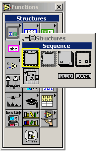
The sequence structure forces the diagrams to execute in a particular order and separate the diagram into logical execution blocks. In this example, the sequence structure will be used to “start” the WinDaq control before it is used. - Insert the selected sequence structure into the Diagram window:
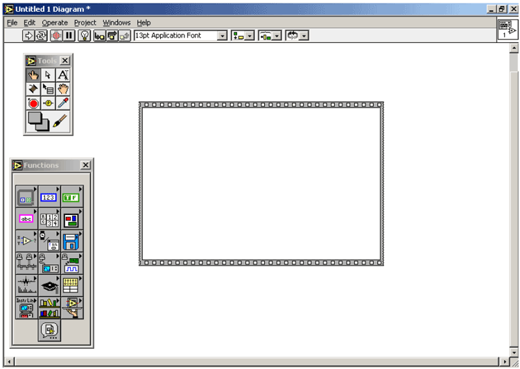
The Diagram window is the source code of the project. The diagram drawn in this window will determine what gets executed, in what order, etc. This is the “behind-the-scenes” work that runs the Front Panel. - Insert an ActiveX Container into the Front Panel
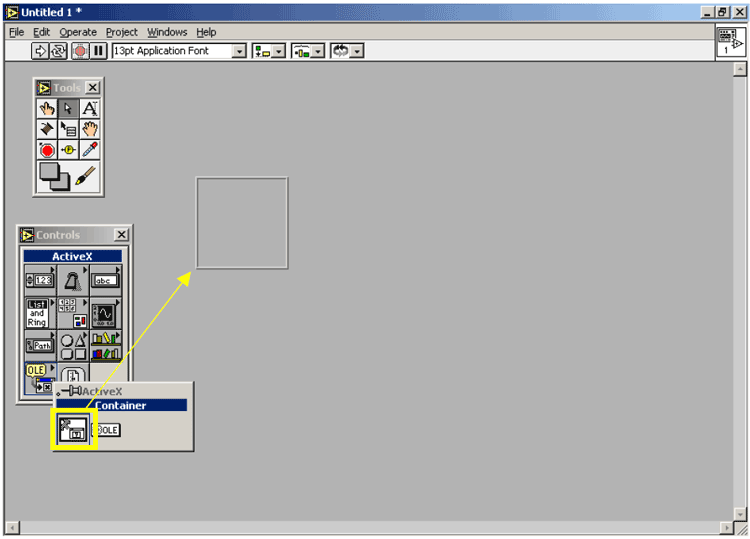
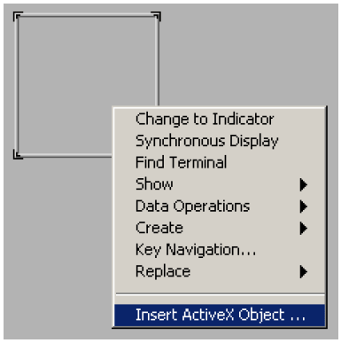
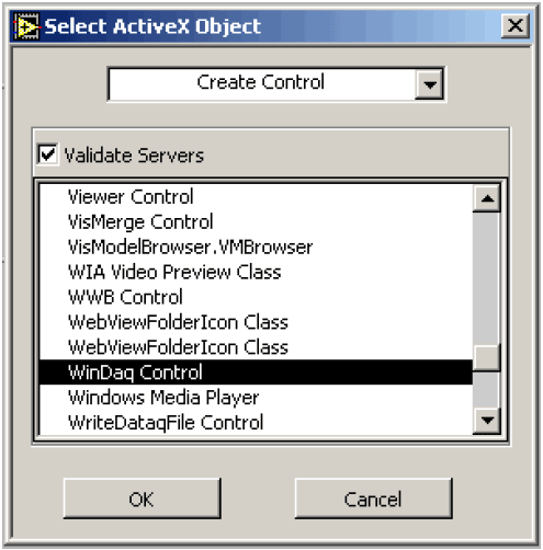
The Front Panel is what will become the User Interface. The ActiveX container is necessary to insert an ActiveX control into LabVIEW. ActiveX controls work on the basis of server-client relationships. Refer to the “Introduction to ActiveX” secondary topic in the LabVIEW online help documentation for a description of how LabVIEW works with ActiveX controls. This section can be found by searching for “ActiveX, introduction” in the index. - Right-click the container and select Insert ActiveX Object….
- Scroll to find WinDaq Control select it, and click OK.
This will give you a list of all currently available ActiveX controls on the system. - In the Diagram window, right-click the newly created control, select Show then Label to display what it is.
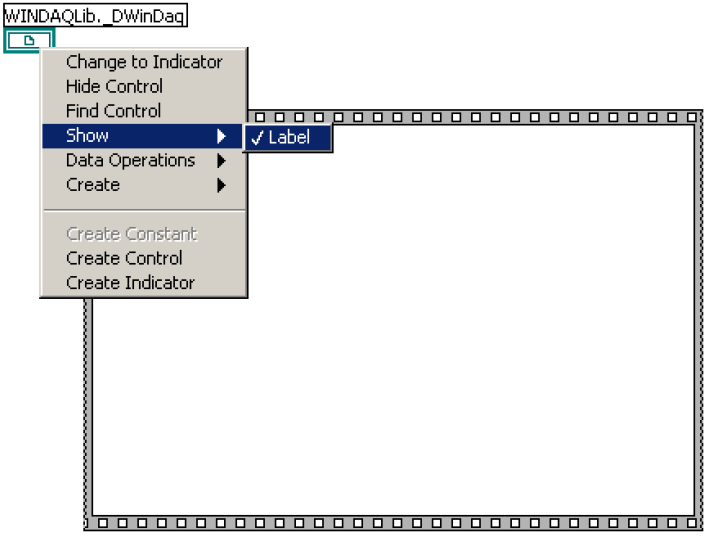
This will make it easier to identify what the object/picture represents. - Click the Wiring tool in the Tools toolbox.
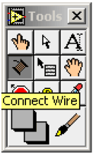
The wiring tool can be used to create “paths” that are to be followed during the execution of the program. These paths tell LabVIEW to take information from one object and send it to another object. - Connect the WinDaq Control to the Sequence.
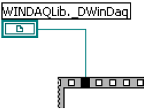
This will make the WinDaq control available to all frames within the sequence. - In the Front Panel, insert a Horizontal Slide from the Controls toolbox.
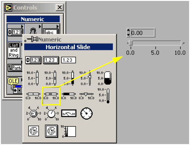
The horizontal slide will be used to select the channel to “watch” (i.e., the channel from which data will be read and displayed onscreen). - In the Tools toolbox, click on the Operate Value tool.
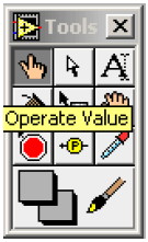
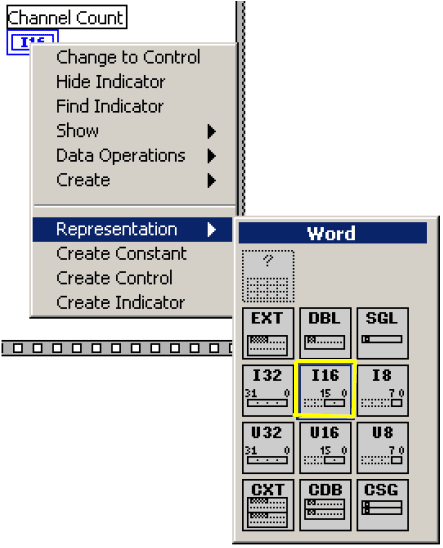
This tool allows you to change some of the object’s properties. This tool is used at runtime to operate the controls in the Front Panel. - Now change the slider’s values from 1 to 2. Then, right-click and change the Representation to I16 (Word).
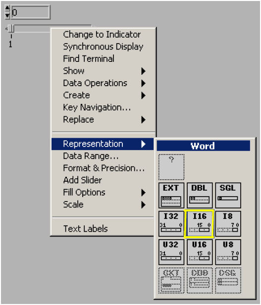
To change the values, click on them and type in new values. The representation is changed to I16(Word) because that is the underlying integer type that most closely matches the WinDaq control’s property that will be used to determine the channel. The data types used by a specific property or method can be found in the ActiveX Controls Help file provided on the DATAQ website. - Insert a Digital Indicator.
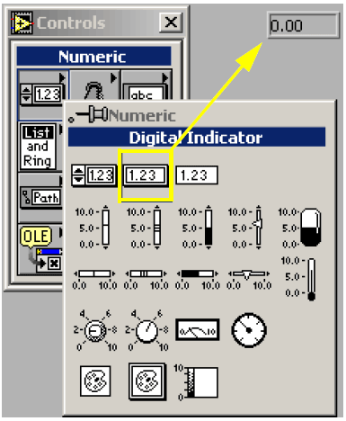
This indicator will only display information to the user, not allow them to change it. This indicator will display the total number of channels. - Insert another Digital Indicator. This indicator will display the actual data coming from the WinDaq control.
- Right-click on each control and label them as follows:
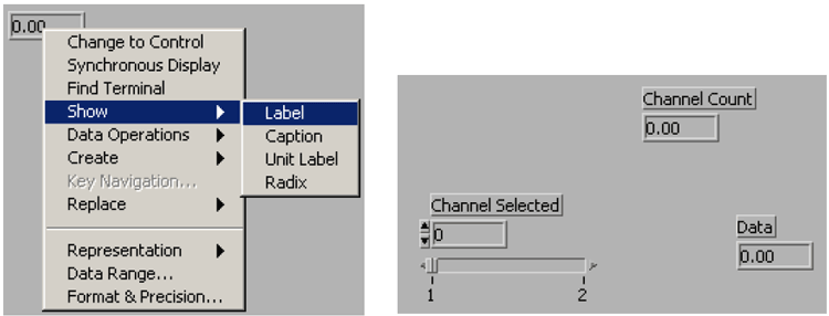
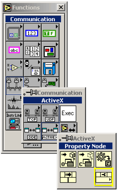
After clicking Label, start typing to set the label. - In the Diagram window on the Functions toolbox, click Communication then ActiveX then Invoke Node.
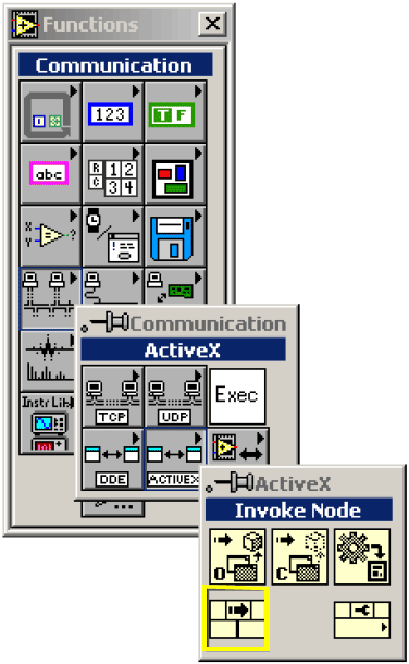
An Invoke Node is an object that calls a method from an ActiveX control. It allows you to give it any data it may need to pass to the method as well as return the results of the method call. - Insert the object inside the sequence and connect a wire from the WinDaq Control (connected to the sequence using the black square on the sequence) to the Reference point of the Invoke Node.
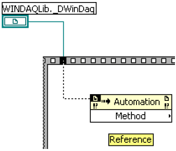
This will allow the Invoke Node to “know” what methods are available, what data needs to be sent, and what data will be returned. - Right-click the Invoke Node and select the Start method.
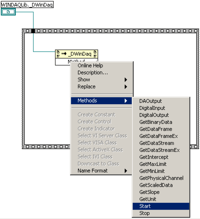
The Start method tells the WinDaq control to start acquiring data. - Right-click the Sequence, then click Add Frame After.
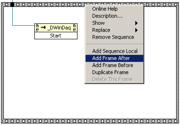
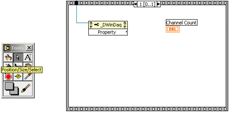
This will add a separate “block” to draw diagrams which will execute after the previous frame. - Insert a Property Node inside the Sequence and connect it to the WinDaq Control with a wire.
- Use the Arrow tool to move the Channel Count object inside the Sequence frame.
- Right-click the Property Node and select the ChannelCount property.
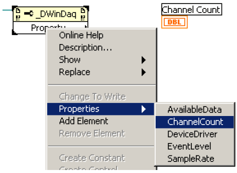
The ChannelCount property returns the total number of channels available to read data from. - Right-click the Channel Count object and change its Representation to I16.
- Right-click the Channel Selected object and create an Attribute Node.
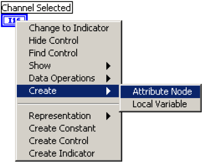
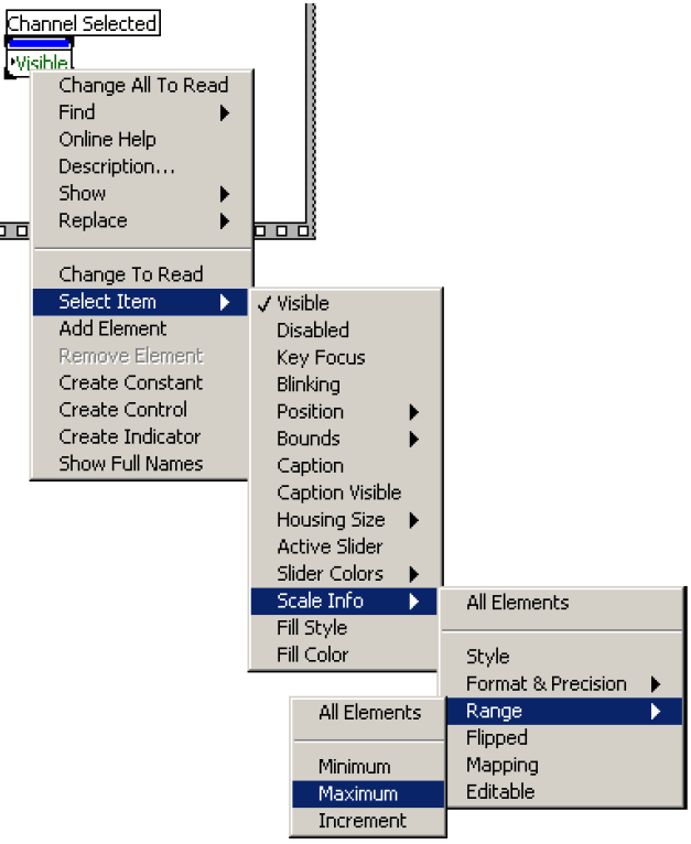
An Attribute Node is “connected” to its parent object and allows you to change the parent’s properties when the program is running. - Move this node inside the sequence. Right-click it and change its property to Maximum.
- Using the Wiring tool, create wires to connect the objects inside the sequence as follows:
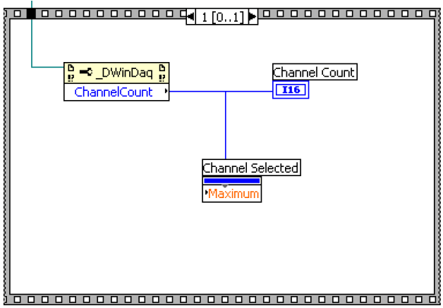
The Attribute Node sets the maximum value of the Channel Selected object. This in turn will prevent the user from trying to read data from a channel that is out-of-bounds. The Channel Count indicator will also display the total number of channels. - Add another frame after this one to the sequence.
- Insert a While Loop inside the sequence.
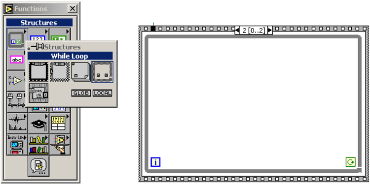
Since events are not supported in the version of LabVIEW this example was created with, a while loop will be used to continuously ask for data from the WinDaq ActiveX control. - Insert an Invoke Node object into the while loop. Move the Channel Selected object and Data object into the while loop.
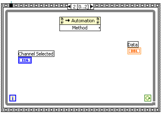
By moving the objects inside the while loop, they will be executed (along with any other steps inside) with every “round” of the while loop. - Create a wire to connect the Invoke Node to the WinDaq Control. Then, right-click it and select the GetScaledData method.
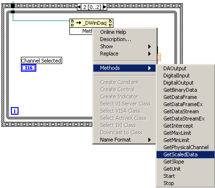
The GetScaledData method will be used to get the data from WinDaq in calibrated engineering units as specified in the software. Refer to the ActiveX Controls Help file for further information on properties and methods of the ActiveX controls. - Insert a Decrement object to decrement the signal from the Channel Selected object to the Data object and connect it as follows:
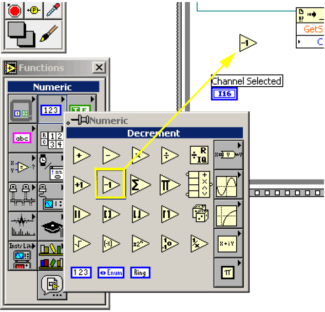
The Channel Selected object will allow the user to select a channel (1 through Maximum). The object will return the user’s selection, but the actual channel is one less because the WinDaq control enumerates the channels zero-based (starting with zero rather than 1). - Connect the Channel Selected object and the Data object as follows:
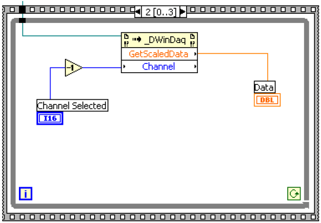
This will allow the Channel Selected to select which channel to get data from and the data returned by GetScaledData will be displayed in the Data indicator. - Insert a Boolean Constant, set it to true using the Operate Value tool by clicking on the object after it is inserted, and connect it to the Conditional Terminal of the while loop.
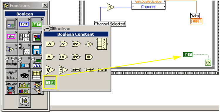
This will cause the while loop to run forever or until the program is forcefully stopped by clicking the Stop button. Normally, a Boolean control is used here so that the program may finish properly. - Add another frame, after this one, to the Sequence.
- Insert an Invoke Node object in the sequence and connect it to the WinDaq Control. Change its method to Stop.
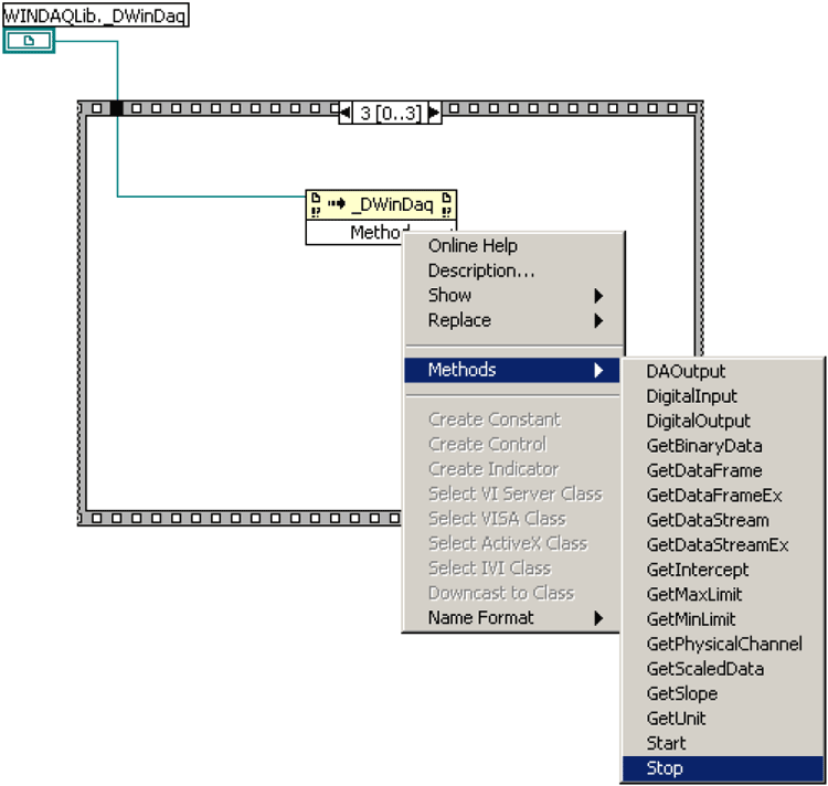
This method tells the WinDaq control to stop acquiring data. This will not be executed as it should because the while loop will never terminate to get to this step. When the program is forcefully stopped, it doesn’t go on to this frame. - Start WinDaq as usual, then go back to LabVIEW, in the Front Panel, and run the project.
You should see the Data indicator displaying the same data as the WinDaq acquisition software. Changing the channel using the Channel Selected object will show the data for that channel.