
 View Cart
 sales@dataq.com
 330-668-1444
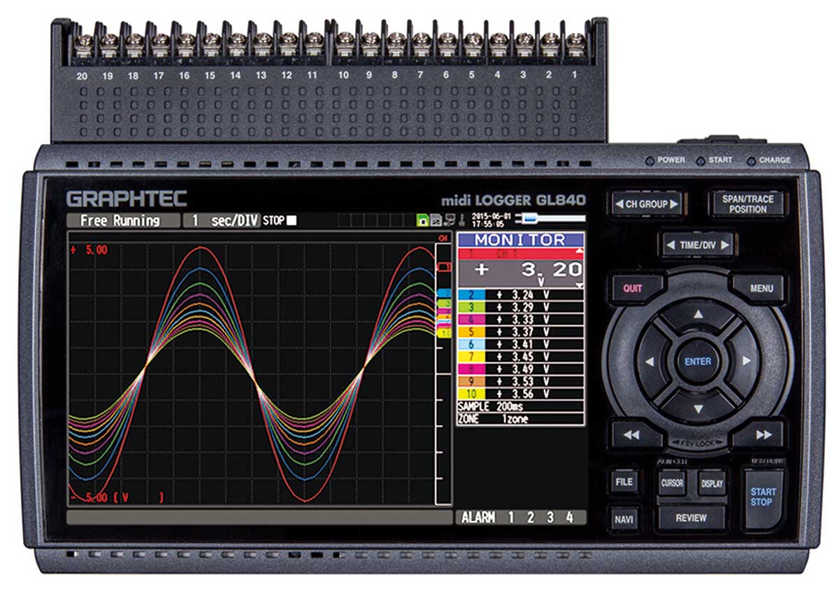
Graphtec Model GL840 with 60-V Isolation
20 to 200-channel Handheld Voltage and Thermocouple Data Logger
- Includes a GL840-M data logger, an AC adapter, and software on CD (Ship to USA only)
- 20 analog input channels, expandable to 200
- Programmable per channel
- ±20 mV to ±100 V over 12 ranges
- Supports direct-connected thermocouples of any type
- Supports direct-connected PT100/PT1000 RTDs
- Full isolation per channel (60V)
- 4 discrete input channels
- Programmable as a group as logic or pulse inputs
- Pulse inputs support counter or frequency inputs
- 4 discrete alarm outputs
- Optional WiFi wireless operation
- Flexible triggering
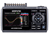
- Built-in, 7-inch color display
- Built-in Web server operation for remote operations
- Removable SD memory support up to 32 GB capacity
- Includes 4 GB of internal non-volatile memory
- Operates either stand-alone or PC-connected
- PC-side software included
- Factory-calibrated. NIST-traceable certificates available in Accessories tab
 Share
Share
Description
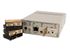
GL840 Voltage and Thermocouple Data Logger system features 20 isolated analog input channels (expandable to 200), 4 discrete inputs, and 4 discrete outputs with extremely flexible triggering conditions. Use the GL840 either stand-alone with a built-in battery compartment or pc-connected via the USB or Ethernet port.
Model GL840 Series is a third-generation data logger product with exceptional price/performance. It’s a 20 analog channel device expandable to 200 channels, augmented by four discrete inputs and outputs. Its discrete inputs can be configured as a group to be either logic inputs or pulse inputs. When configured for pulse, each of the four channels can be configured to measure frequency or to count. The four discrete outputs are alarms that can be triggered by a variety of easily-defined analog and pulse/discrete input channel conditions. The 20 GL840 analog input channels may each be configured to measure a direct connected voltage in the range of 20 mV to 100 V full scale across 12 ranges, a direct-connected thermocouple of any type, or a 3-wire PT100 or PT1000 RTD. Each of the GL840’s analog input channels is electrically isolated from other channels and from power ground allowing off-ground measurements using shunts, as well as powered or grounded thermocouples. Model GL840-M supports up to 60 Vp-p common mode. The most powerful GL840 feature is its triggering flexibility. Data recording can be independently started or stopped as a function of analog and pulse/discrete signal level (single or windowed), alarm, date and time, and day-of-the-week. Triggers can also be configured to operate only once, or to automatically repeat. The ability of the GL840 to adapt to virtually any desired trigger condition allows the instrument to operate unattended for long periods of time with complete autonomy.
The GL840 operates either connected to a PC or entirely stand-alone. Connection to a PC may be over a standard Ethernet, USB, or optional wireless connection. Each connection approach may take advantage of supplied PC-side software to configure, acquire, display, and record digitized information for storage directly to the PC’s HDD. Acquired data may be retrieved for review and analysis after recording, including the ability to export to Microsoft Excel. Using the GL840’s built-in Ethernet port or wireless option enables the instrument’s networking features, allowing it to be remotely configured and managed using the standard Web browser of any computer or smart phone. The GL840 is provided with 4 GB of non-volatile memory embedded inside the instrument. The instrument supplies an external SD card slot for additional storage if needed.
The measurement reach of the GL840 is further extended by use of GS Sensor accessories that can be either connected directly to the GL840 or wirelessly accessed with the B-568 wireless option using the GL100-WL. Extended measurements of temperature/humidity, acceleration, CO2, illuminance, ac current, and more are available using GS Sensors.
Accessories
Description
250 Ω ±0.1% Precision, Metal Film, 1/2W, Axial Resistor
Exceptionally low noise; typically 0.10 μV/V
Low voltage coefficient to ±5 ppm/V
Flame retardant coating. RoHS
compliant. Learn More

Description
NIST-traceable calibration certificate for all Graphtec GL Data Loggers. Does not include data. This item is NOT included with a new unit and should be purchased at the same time as the new unit. Shipping charges will apply if not ordered at time of logger purchase. Learn more about Calibrating your device.
Description
NIST-traceable calibration certificate for all Graphtec GL Data Loggers. Includes data. This item is NOT included with a new unit and should be purchased at the same time as the new unit. Shipping charges will apply if not ordered at time of logger purchase. Learn more about Calibrating your device.
Description
ISO:17025 calibration certificate for all Graphtec GL840 Data Loggers. Includes data. This item is NOT included with a new unit and should be purchased at the same time as the new unit. Shipping charges will apply if not ordered at time of logger purchase. This item DOES NOT ship same-day. Please allow 4 week lead time. Learn more about Calibrating your device.
Description
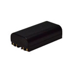
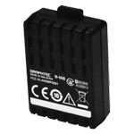
One (1) 7.2V/2900mAh lithium battery pack. Please Note: Continental U.S. shipping ONLY.
Description
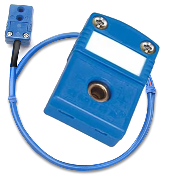
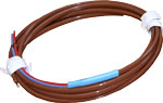
T-type thermocouple adapter (wires on the other end) to save time, preserve the integrity of themocouple connections and prevent mis-wires. Compatible with TC-T/4 thermocouple with connector
Description
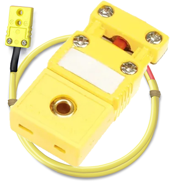
K-type thermocouple adapter (wires on the other end) to save time, preserve the integrity of themocouple connections and prevent mis-wires. Compatible with TC-K/4 thermocouple with connector
Description
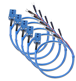
Pack of 5 T-type thermocouple adapters (fork connector the other end) to save time, preserve the integrity of themocouple connections and prevent mis-wires
Description
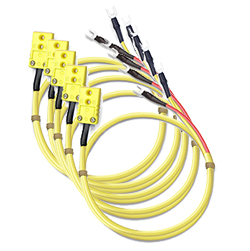
Pack of 5 K-type thermocouple adapters (fork connector the other end) to save time, preserve the integrity of themocouple connections and prevent mis-wires
Description
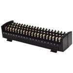
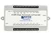
20-channel standard input terminal for GL840 data loggers. Please note: Use of one or more B-564 input terminals with the GL840-WV forces all channels to the low common mode voltage spec of 60V. Use model B-565 to maintain the 300V spec across all channels.
Description
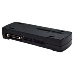
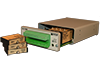
Extension terminal base for GL840 and GL860 data loggers. Includes base unit, connection plate, and screws.
Description
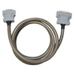
50 cm extension terminal cable for GL840 data loggers.
Description
2 m extension terminal cable for GL840 data loggers.
Description
Wireless communication option for GL260 and GL860 data loggers. 802.11/b/g/n. Attachment of this wireless option to the instrument prevents the use of an external SD memory card, with only the internal 4 GB non-volatile memory available for data storage.
Description
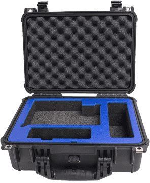
Carrying Case. Interior padding and rugged exterior for safe transportation of your GL840 and GL860 data logger.
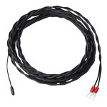
J, K and T Thermocouple Wires
Teflon® coated or High Temp Glassbraisd J, K and T Thermocouple Wires in various length
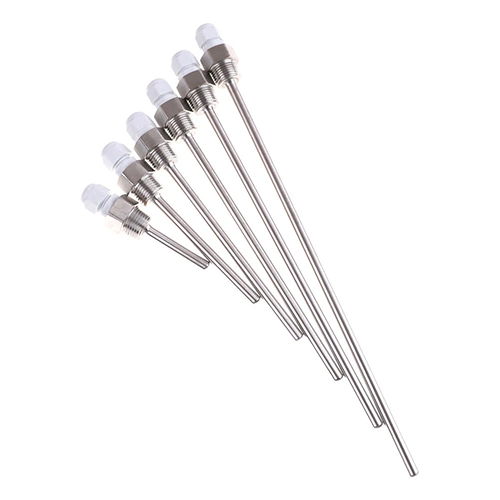
50-500mm Thermowells
8mm diameter, 50-500mm length, 1/2" MNTP, stainless thermowells with cable gland to protect your thermocouples
Description
Thermistor Temperature sensor connects to model GS-4TSR. Measures -40 to 105 °C.
Description
Thermistor Temperature sensor connects to model GS-4TSR. Ultra thin. Measures -40 to 120 °C.
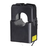
Description
Clamp-on AC Current sensor for GS-DPA-AC. 200 A AC current.
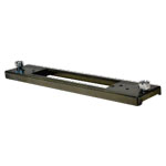
Description
DIN Rail Mounting Adapter for GL260 and GL860 models.
Software
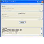
GBD to WDH
File Conversion
FREE Graphtec to WinDaq High Resolution (GBD - to - WDH) File Conversion Utility (beta version) converts files recorded with a Graphtec device to WinDaq Playback for analysis.
Graphtec Downloads
Data Logger Software
Visit the Support Download page at Graphtec for software (The link below takes you to another site).
Specifications
| Analog Inputs | ||||||||||||||||||||||||||||||||||||||||||||||||||||||||||||||||||||||||||||||||||||||||||||||||||
| Number of Channels: | Maximum 200ch available for 20ch/1 terminal or extension unit | |||||||||||||||||||||||||||||||||||||||||||||||||||||||||||||||||||||||||||||||||||||||||||||||||
| GS sensor and terminal/adapter connection terminal: | One module Optional (GS sensor and terminal / adapter ) connections only |
|||||||||||||||||||||||||||||||||||||||||||||||||||||||||||||||||||||||||||||||||||||||||||||||||
| Data backup functions: | Setup parameters: EEPROM Clock: Lithium battery |
|||||||||||||||||||||||||||||||||||||||||||||||||||||||||||||||||||||||||||||||||||||||||||||||||
| Clock accuracy: (23°C environment) |
±0.002% (accurate within about 50 seconds per month) | |||||||||||||||||||||||||||||||||||||||||||||||||||||||||||||||||||||||||||||||||||||||||||||||||
| Operating environment: | 0 to 45°C, 5 to 85% RH (0 to 40°C when operated in batteries/15 to 35°C when battery is charging) |
|||||||||||||||||||||||||||||||||||||||||||||||||||||||||||||||||||||||||||||||||||||||||||||||||
| Withstand voltage: | Between each input ch and GND terminal: 350Vpp 1 minute Between each input terminals: 350Vp-p 1 minute |
|||||||||||||||||||||||||||||||||||||||||||||||||||||||||||||||||||||||||||||||||||||||||||||||||
| Power supply: | AC adapter: 100 to 240 VAC, 50 to 60 Hz DC input: 8.5 to 24 VDC (26.4 V max.) Battery pack (option): 7.2 VDC (2900 mAh), two packs can be mounted |
|||||||||||||||||||||||||||||||||||||||||||||||||||||||||||||||||||||||||||||||||||||||||||||||||
| Power Consumption: | AC Power consumption (when AC adapter is used)
DC Power consumption
*Set the LCD to “Bright” as normal condition. |
|||||||||||||||||||||||||||||||||||||||||||||||||||||||||||||||||||||||||||||||||||||||||||||||||
| External Dimensions: | 240×158×52.5mm (not including protruding parts) | |||||||||||||||||||||||||||||||||||||||||||||||||||||||||||||||||||||||||||||||||||||||||||||||||
| Weight: | 1010g (AC adapter and battery are not included, but one terminal unit is included) | |||||||||||||||||||||||||||||||||||||||||||||||||||||||||||||||||||||||||||||||||||||||||||||||||
| Vibration-tested conditions: | Equivalent to automobile parts Type 1 Category A classification | |||||||||||||||||||||||||||||||||||||||||||||||||||||||||||||||||||||||||||||||||||||||||||||||||
| Memory devices | ||||||||||||||||||||||||||||||||||||||||||||||||||||||||||||||||||||||||||||||||||||||||||||||||||
| Memory capacity: | SD CARD Slot: 2 (Compatible with SDHC, up to approx. 32GB memory available) • Approx. 4GB internal, non volatile memory • Possible to save up to 2GB for one file |
|||||||||||||||||||||||||||||||||||||||||||||||||||||||||||||||||||||||||||||||||||||||||||||||||
| Memory contents: | Setup conditions, Measured data, Screen copy | |||||||||||||||||||||||||||||||||||||||||||||||||||||||||||||||||||||||||||||||||||||||||||||||||
| PC I/F | ||||||||||||||||||||||||||||||||||||||||||||||||||||||||||||||||||||||||||||||||||||||||||||||||||
| Interface types: | Ethernet (10BASE-T/100BASE-TX) USB 2.0 Wireless LAN (Option) |
|||||||||||||||||||||||||||||||||||||||||||||||||||||||||||||||||||||||||||||||||||||||||||||||||
| Functions: | Data transfer to the PC (realtime, SD memory card data) PC control of the GL840 Control of wireless sensor GL100GL100-WL, Data capture (when connected to the wireless LAN: up to 5 units) |
|||||||||||||||||||||||||||||||||||||||||||||||||||||||||||||||||||||||||||||||||||||||||||||||||
| Ethernet functions: (10BASE-T/100BASE-TX) |
Web server functions: Displays the screen images. FTP server function: Transfer and delete the captured data in the SD memory card. FTP client function: Back up the captured data to the FTP server. NTP client function: Time-synchronize the NTP server. DHCP client function: IP address automatic acquisition DHCP client function : Automatically retrieves the IP address E-mail function: Send and receive the e-mail |
|||||||||||||||||||||||||||||||||||||||||||||||||||||||||||||||||||||||||||||||||||||||||||||||||
| USB functions: | USB drive mode: Transfer and delete the captured data in the SD memory card. | |||||||||||||||||||||||||||||||||||||||||||||||||||||||||||||||||||||||||||||||||||||||||||||||||
| Realtime data transfer speed: | 10 ms/1 ch maximum (dependant on number of channels). | |||||||||||||||||||||||||||||||||||||||||||||||||||||||||||||||||||||||||||||||||||||||||||||||||
| Monitor | ||||||||||||||||||||||||||||||||||||||||||||||||||||||||||||||||||||||||||||||||||||||||||||||||||
| Display: | 7-inch TFT color LCD (WVGA: 800 × 480 dots) | |||||||||||||||||||||||||||||||||||||||||||||||||||||||||||||||||||||||||||||||||||||||||||||||||
| Displayed languages: | Japanese, English, French, German, Chinese, Korean, Russian, Spanish | |||||||||||||||||||||||||||||||||||||||||||||||||||||||||||||||||||||||||||||||||||||||||||||||||
| Backlight life: | 50,000 hrs (until the brightness is reduced to 50%), It varies with operating environment | |||||||||||||||||||||||||||||||||||||||||||||||||||||||||||||||||||||||||||||||||||||||||||||||||
| Backlight: | Screen saver function provided (10, 30 sec., 1, 2, 5, 10, 30, 60 min.) | |||||||||||||||||||||||||||||||||||||||||||||||||||||||||||||||||||||||||||||||||||||||||||||||||
| Input Unit Specifications | ||||||||||||||||||||||||||||||||||||||||||||||||||||||||||||||||||||||||||||||||||||||||||||||||||
| Number of input channels: | 20ch (200ch available when used with the extension terminal base). Possible to direct-connect or connect with the extension terminal connection cable (sold separately) between the GL840 and terminal unit, or between terminal units. | |||||||||||||||||||||||||||||||||||||||||||||||||||||||||||||||||||||||||||||||||||||||||||||||||
| Input terminal type: | M3 screw type terminals (Rectangular flat washer) | |||||||||||||||||||||||||||||||||||||||||||||||||||||||||||||||||||||||||||||||||||||||||||||||||
| Input method: | Photo MOS relay scanning system All channels isolated, balanced input Terminal b to be used to connect the resistance temperature detector is shorted within all channels. |
|||||||||||||||||||||||||||||||||||||||||||||||||||||||||||||||||||||||||||||||||||||||||||||||||
| Scan speed: | 10 ms/1 ch maximum | |||||||||||||||||||||||||||||||||||||||||||||||||||||||||||||||||||||||||||||||||||||||||||||||||
| Measurement ranges: | Voltage: 20, 50, 100, 200, 500 mV; 1, 2, 5, 10, 20, 50, 100 V; 1-5 V F.S. Thermocouples : K, J, E, T, R, S, B, N, W (WRe5-26) Resistance temperature detector: Pt100, JPt100, Pt1000 (IEC751) Temperature range : 100°C, 500°C, 2000°C (150°F, 750°F, 3000°F) Humidity: 0 to 100% (voltage 0 to 1 V scaling conversion) fixed (requires B-530) |
|||||||||||||||||||||||||||||||||||||||||||||||||||||||||||||||||||||||||||||||||||||||||||||||||
| Measurement accuracy: 23°C ±5°C; When 30 minutes or more have elapsed after power was switched on; Sampling 1 s/10 ch; Filter ON (10); GND connected |
Voltage: 0.1% of F.S. Temperature Thermocouple
* Thermocouple diameters T, K: 0.32 φ, others: 0.65 φ Resistance temperature detector:
*3-wire system Temperature Range:
*Measurement accuracy does not change due to the temperature range |
|||||||||||||||||||||||||||||||||||||||||||||||||||||||||||||||||||||||||||||||||||||||||||||||||
| Reference contact compensation accuracy: | Internal/External switching | |||||||||||||||||||||||||||||||||||||||||||||||||||||||||||||||||||||||||||||||||||||||||||||||||
| A/D converter: | Method :ΔΣ method Resolution :16-bit (Effective resolution: About 1/40,000 of the +/- range) |
|||||||||||||||||||||||||||||||||||||||||||||||||||||||||||||||||||||||||||||||||||||||||||||||||
| Temperature coefficient: | Gain: 0.01% of F.S./°C Zero: 0.02% of F.S./°C (Occurs when sampling speed is 10, 20, or 50 ms.) |
|||||||||||||||||||||||||||||||||||||||||||||||||||||||||||||||||||||||||||||||||||||||||||||||||
| Input resistance: | 1 MΩ ±5% | |||||||||||||||||||||||||||||||||||||||||||||||||||||||||||||||||||||||||||||||||||||||||||||||||
| Allowable signal source resistance: | Within 300Ω | |||||||||||||||||||||||||||||||||||||||||||||||||||||||||||||||||||||||||||||||||||||||||||||||||
| Maximum permissible input voltage: | Between +/– input terminals: 20mV to 1V range (60Vp-p); 5V to 100V range (110Vp-p) Between input terminal/input terminal: 60 Vp-p Between input terminal/GND: 60 Vp-p |
|||||||||||||||||||||||||||||||||||||||||||||||||||||||||||||||||||||||||||||||||||||||||||||||||
| Withstand voltage: | Between input terminal/input terminal: 350 Vp-p 1 minute Between input terminal/GND: 350 Vp-p 1 minute |
|||||||||||||||||||||||||||||||||||||||||||||||||||||||||||||||||||||||||||||||||||||||||||||||||
| Insulation resistance: | Between input terminal/GND: 50MΩ or more (at 500 VDC) | |||||||||||||||||||||||||||||||||||||||||||||||||||||||||||||||||||||||||||||||||||||||||||||||||
| Common mode rejection ratio: | 90 dB or more (50/60 Hz; signal source 300Ω or less) | |||||||||||||||||||||||||||||||||||||||||||||||||||||||||||||||||||||||||||||||||||||||||||||||||
| Noise: | 48 dB or more (with +/– terminals shorted) | |||||||||||||||||||||||||||||||||||||||||||||||||||||||||||||||||||||||||||||||||||||||||||||||||
| Filter: | Off, 2, 5, 10, 20, 40 Filter operation is on a moving average basis. The average value of the number of set samples is used. If the sample interval exceeds 30 seconds, the average value of data obtained in a sub-sample (30 seconds) is used. |
|||||||||||||||||||||||||||||||||||||||||||||||||||||||||||||||||||||||||||||||||||||||||||||||||
| Function Specifications | ||||||||||||||||||||||||||||||||||||||||||||||||||||||||||||||||||||||||||||||||||||||||||||||||||
| Display screen: | Waveform + Digital screen, All Waveform screen, Digital + Calculation Display screen, Expanded digital screen * Can be switched using the dedicated key (toggle operation) * For the Expanded Digital screen, the number of channels and the display channel must be specified * The waveform is not rewritten due to the change of the TIME / DIV. |
|||||||||||||||||||||||||||||||||||||||||||||||||||||||||||||||||||||||||||||||||||||||||||||||||
| Sampling interval: | 10 ms/1 ch maximum (GBD/CSV-formatted) 10, 20, 50, 100, 125, 200, 250, 500 ms; 1, 2, 5, 10, 20, 30 sec.; 1, 2, 5, 10, 20, 30 min.; 1 hour External * The settings of 125 ms or below can be used depending on the input settings and the measuring channel. |
|||||||||||||||||||||||||||||||||||||||||||||||||||||||||||||||||||||||||||||||||||||||||||||||||
| EU (scaling function): | 4 points can be set for each channel The temperature range scaling function is available. |
|||||||||||||||||||||||||||||||||||||||||||||||||||||||||||||||||||||||||||||||||||||||||||||||||
| Functions during capture: | Confirmation of the captured data Saving of data between cursors Replacement of the SD memory card * When the wireless sensor (GL100-WL) is connected, the sample interval among 10, 20, and 50ms cannot be replaced during recording. |
|||||||||||||||||||||||||||||||||||||||||||||||||||||||||||||||||||||||||||||||||||||||||||||||||
| Data save function: | Capture destination: SD memory card (Available both slot 1 and 2) Captured data: Settings, Screen data, Measurement data |
|||||||||||||||||||||||||||||||||||||||||||||||||||||||||||||||||||||||||||||||||||||||||||||||||
| Capture function: | Function: OFF, Ring recording, Relay recording | |||||||||||||||||||||||||||||||||||||||||||||||||||||||||||||||||||||||||||||||||||||||||||||||||
| Ring recording: | Number of recording points: 1000 to 2000000 When ring capture is ON, the memory space that can be used for capture is one-third of the free space |
|||||||||||||||||||||||||||||||||||||||||||||||||||||||||||||||||||||||||||||||||||||||||||||||||
| Relay recording: | The data is continuously recorded in 2GB-separated files without missing data. | |||||||||||||||||||||||||||||||||||||||||||||||||||||||||||||||||||||||||||||||||||||||||||||||||
| Replaying data: | GBD/CSV-formatted data file (only data captured in this GL840) | |||||||||||||||||||||||||||||||||||||||||||||||||||||||||||||||||||||||||||||||||||||||||||||||||
| Calculation between channels: | Calculation type: Four arithmetic operations (+, -, ×, ÷) Target input: Analog CH1 to CH200 GS sensor and terminal/adapter: CH1 to CH8 Wireless sensor: CH1-1 to CH5-8 |
|||||||||||||||||||||||||||||||||||||||||||||||||||||||||||||||||||||||||||||||||||||||||||||||||
| Statistical calculation: | Statistical calculation type: Average value, peak value, maximum value, minimum value, root mean square value Number of calculations: Two arithmetic operations can be set to each channel Calculation method: Real-time calculation and specified between cursors (during replay) * Real-time calculation results are displayed on the Digital screen + Calculation Display screen. |
|||||||||||||||||||||||||||||||||||||||||||||||||||||||||||||||||||||||||||||||||||||||||||||||||
| Search functions: | Function: Search the captured data for the required number of points Search type: Channel Pulse, Logic, Level, Alarm search |
|||||||||||||||||||||||||||||||||||||||||||||||||||||||||||||||||||||||||||||||||||||||||||||||||
| Annotation input function: | Function: A comment can be entered for each channel Input table characters: Alphanumerics Number of characters: 31 (The number of characters can be displayed on the screen is up to eight characters.) |
|||||||||||||||||||||||||||||||||||||||||||||||||||||||||||||||||||||||||||||||||||||||||||||||||
| Navigation function: | Easy capture measurement, easy trigger setting, wireless LAN setting functions | |||||||||||||||||||||||||||||||||||||||||||||||||||||||||||||||||||||||||||||||||||||||||||||||||
| Trigger/Alarm Functions | ||||||||||||||||||||||||||||||||||||||||||||||||||||||||||||||||||||||||||||||||||||||||||||||||||
| Repeat Trigger: | Off, On | |||||||||||||||||||||||||||||||||||||||||||||||||||||||||||||||||||||||||||||||||||||||||||||||||
| Trigger types: | Start: Data capture starts when a trigger is generated Stop: Data capture stops when a trigger is generated |
|||||||||||||||||||||||||||||||||||||||||||||||||||||||||||||||||||||||||||||||||||||||||||||||||
| Trigger conditions: | Start: Off, Level, Alarm, External, Time Stop: Off, Level, Alarm, External, Time |
|||||||||||||||||||||||||||||||||||||||||||||||||||||||||||||||||||||||||||||||||||||||||||||||||
| Trigger judgment modes: | Combination: Level OR, Level AND, Edge OR, Edge AND Analog channel judgment mode: H (↑), L (↓), Window In, Window Out Logic channel judgment mode: H (↑), L (↓) Pulse channel judgment mode: H (↑), L (↓), Window In, Window Out |
|||||||||||||||||||||||||||||||||||||||||||||||||||||||||||||||||||||||||||||||||||||||||||||||||
| Alarm judgment modes: | Combination: Analog, Logic or “AND” / “OR” of pulse Analog judgment: H (↑), L (↓), Window In, Window Out Logic judgment: Pattern Pulse judgment: H (↑), L (↓), Window In, Window Out |
|||||||||||||||||||||||||||||||||||||||||||||||||||||||||||||||||||||||||||||||||||||||||||||||||
| External Input/Output Functions | ||||||||||||||||||||||||||||||||||||||||||||||||||||||||||||||||||||||||||||||||||||||||||||||||||
| Input/output types: | Trigger input (1 ch) or External sampling input (1 ch) Logic input (4 ch) or Pulse input (4 ch) Alarm output (4 ch) * Switch between Logic and Pulse * Switch between Trigger and External sampling. * The Input/output cable for GL B-513 (option) is required to use the external output function. |
|||||||||||||||||||||||||||||||||||||||||||||||||||||||||||||||||||||||||||||||||||||||||||||||||
| Input specifications: | Input voltage range: 0 to +24 V (single-ended ground input) Input signal: No-voltage contact (a-contact, b-contact, NO, NC), Open collector, Voltage input Input threshold voltage: Approx. +2.5 V Hysteresis: Approx. 0.5 V (+2.5 to + 3 V) |
|||||||||||||||||||||||||||||||||||||||||||||||||||||||||||||||||||||||||||||||||||||||||||||||||
| Alarm output specifications: | Output format: Open collector output (5 V, pull-up resistance 10KΩ) <Maximum ratings of output transistor> • Collector-GND voltage: 30 V • Collector current: 0.5 A • Collector dissipation: 0.2 W Output conditions: Level judgment, window judgment, logic pattern judgment, pulse judgment |
|||||||||||||||||||||||||||||||||||||||||||||||||||||||||||||||||||||||||||||||||||||||||||||||||
| Pulse input: | Revolutions mode (engines, etc.): Counts the number of pulses per sampling interval, and converts them to RPM. Set the number of pulses per revolution during revolution. Spans : 50, 500, 5000, 50 k, 500 k, 5 M, 50 M, 500 M PRM/F.S. Counts mode (electric meters, etc.): Counts the number of pulses for each sampling interval from the start of measurement. Spans : 50, 500, 5000, 50 k, 500 k, 5 M, 50 M, 500 M C/F.S. Inst. mode: Counts the number of pulses for each sampling interval. Resets the count value after each sampling interval. Spans : 50, 500, 5000, 50 k, 500 k, 5 M, 50 M, 500 M C/F.S. Maximum input frequency: 50kHz Maximum number of count: 50kC/sampling (16-bit counter) |
|||||||||||||||||||||||||||||||||||||||||||||||||||||||||||||||||||||||||||||||||||||||||||||||||
| Connectable sensor, terminal, adapter: | Number of GS sensors and terminals/adapter connection terminals: 1 | |||||||||||||||||||||||||||||||||||||||||||||||||||||||||||||||||||||||||||||||||||||||||||||||||
| Generic name: GS sensor and terminal/adapter | GS-TH: Temperature and humidity sensor GS-4TSR: 4CH thermistor terminal GS-LXUV: Illuminance / ultraviolet sensor GS-DPA: Branch adapter for GS GS-DPA-AC: Adapter for AC current sensor GS-CO2: CO2 sensor GS-3AT: 3-axis acceleration / temperature sensor GS-4VT: 4CH voltage / temperature terminal * The items above are optional accessories. Sampling: 500 ms to 1 hour * Specific setting is not required. It is synchronized to the setting of the GL840. |
|||||||||||||||||||||||||||||||||||||||||||||||||||||||||||||||||||||||||||||||||||||||||||||||||
| Control Software | ||||||||||||||||||||||||||||||||||||||||||||||||||||||||||||||||||||||||||||||||||||||||||||||||||
| Compatible OS: | Windows8.1/Windows8/Windows7/Windows Vista | |||||||||||||||||||||||||||||||||||||||||||||||||||||||||||||||||||||||||||||||||||||||||||||||||
| Function: | Main unit control, realtime data capture, data conversion | |||||||||||||||||||||||||||||||||||||||||||||||||||||||||||||||||||||||||||||||||||||||||||||||||
| Number of groups: | 4 groups MAX | |||||||||||||||||||||||||||||||||||||||||||||||||||||||||||||||||||||||||||||||||||||||||||||||||
| Number of CHs per group: | Up to number of connected module | |||||||||||||||||||||||||||||||||||||||||||||||||||||||||||||||||||||||||||||||||||||||||||||||||
| Max number of channels: | 1000 ch maximun | |||||||||||||||||||||||||||||||||||||||||||||||||||||||||||||||||||||||||||||||||||||||||||||||||
| Settings: | AMP settings, capture settings, trigger/alarm settings, report settings, others | |||||||||||||||||||||||||||||||||||||||||||||||||||||||||||||||||||||||||||||||||||||||||||||||||
| Captured data: | Realtime data (CSV, GBD Binary) Data in SD memory card (CSV, GBD binary) |
|||||||||||||||||||||||||||||||||||||||||||||||||||||||||||||||||||||||||||||||||||||||||||||||||
| Display: | Analog waveforms, logic waveforms, pulse waveforms, digital values | |||||||||||||||||||||||||||||||||||||||||||||||||||||||||||||||||||||||||||||||||||||||||||||||||
| Display modes: | Y-T View, Digital View, X-Y View between Cursors (only during replay) | |||||||||||||||||||||||||||||||||||||||||||||||||||||||||||||||||||||||||||||||||||||||||||||||||
| File conversion: | Between cursors, All data | |||||||||||||||||||||||||||||||||||||||||||||||||||||||||||||||||||||||||||||||||||||||||||||||||
| Monitor functions: | Alarm monitor enables sending of email to the specified address | |||||||||||||||||||||||||||||||||||||||||||||||||||||||||||||||||||||||||||||||||||||||||||||||||
| Statistic/History: | Displays max, min and average values | |||||||||||||||||||||||||||||||||||||||||||||||||||||||||||||||||||||||||||||||||||||||||||||||||
| Report function: | Enables creation of daily or monthly files | |||||||||||||||||||||||||||||||||||||||||||||||||||||||||||||||||||||||||||||||||||||||||||||||||
| E-mail function: | E-mail sent to specified address on alarm | |||||||||||||||||||||||||||||||||||||||||||||||||||||||||||||||||||||||||||||||||||||||||||||||||
Articles
Back-up GL820 and GL900 Data Using Windows Built-in FTP Server
Convert GBD files (created by Graphtec Data Loggers) to WDH (WinDaq) files
Sub-zero Thermocouple Measurements
Boot Your Graphtec Data Logger in USB Drive Mode
Wireless Capability of GL240 and GL840 Graphtec Data Loggers
Convert GBD files (created by Graphtec Data Loggers) to WDH (WinDaq) files
Videos
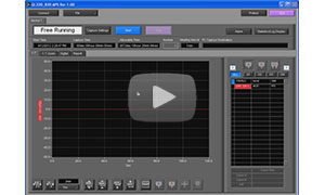
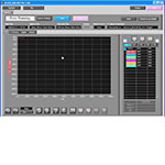
Graphtec APS Software
APS PC-based software provides access to all the features on the front panel, and more.
Similar Products
Quick Product Comparison
| Model | Analog channels |
Expandable* | Measurement Range† |
Thermocouple Support |
Max Sample Rate (Hz) |
ADC Resolution |
Digital I/O |
Interface | Data Storage | Price |
| DI-2008 | 8 | Yes | A | Yes | 200 | 16 | 7 Bi | USB | PC | $499 |
| DI-808 | 8 | - | A | Yes | 40 | 16 | 4 In 4 Out | Ethernet | Internal, USB flash, Cloud | $995 |
| DI-4718B-U | 8 | - | C† | Yes (DI-8B) | 160,000 | 12 to 16 | 2 In | USB | PC or USB flash | $795 |
| DI-4718B-E | 8 | - | C† | Yes (DI-8B) | 160,000 | 12 to 16 | 2 In | USB, Ethernet | PC or USB flash | $695 |
| GL240 | 10 | - | B | Yes | 100 | 16 | 4 In 4 Out | USB | PC, USB flash, Internal, Cloud | $995 |
| GL840-M | 20 | Yes | B | Yes | 100 | 16 | 4 In 4 Out | USB, Ethernet | PC, USB flash, Internal, Cloud | $2345 |
| DI-718B-US | 8 | - | C | Yes (DI-8B) | 14,400 | 14 | 2 In | USB | PC or SD Card | $695 |
| DI-718B-ES | 8 | - | C | Yes (DI-8B) | 14,400 | 14 | 2 In | Ethernet | PC or SD Card | $895 |
*Expansion capabilities dependent on model.
†Use the following chart to determine Measurement Ranges:
| A | B | C* |
| ±10 mV ±25 mV ±50 mV ±100 mV ±250 mV ±500 mV ±1 V ±2.5 V ±5 V ±10 V ±25 V ±50 V TC-J TC-K TC-T TC-B TC-R TC-S TC-E TC-N |
±20 mV ±50 mV ±100 mV ±200 mV ±500 mV ±1 V ±2 V ±5 V ±10 V ±20 V ±50 V ±100 V 1-5 V |
±10 mV ±50 mV ±100 mV ±1 V ±5 V ±10 V ±20 V ±40 V ±60 V |
*Dependent on 8B module.